EasyManua.ls Logo

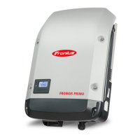
Fronius Primo 10.0-1 208-240 User Manual

Fronius Primo 10.0-1 208-240
58 pages
To Next Page IconTo Next Page
Page #1 background imageLoading...
Page #1 background image
/ Perfect Charging / Perfect Welding / Solar Energy
Fronius Primo 208-240
3.8-1 / 5.0-1 / 6.0-1
7.6-1 / 8.2-1
10.0-1 / 11.4-1
12.5-1 / 15.0-1
Operating Instructions
Inverter for grid-connected photo-
voltaic systems
Instructions de service
Onduleur pour installations photo-
voltaïques connectées au réseau
Manual de instrucciones
Inversores para instalaciones foto-
voltaicas acopladas a la red
EN-USFR
ES
www.youtube.com/FroniusSolar
LEARN MORE WITH
OUR HOW-TO VIDEOS
42,0410,2116 014-15122015

Table of Contents

Other manuals for Fronius Primo 10.0-1 208-240

Questions and Answers:

Fronius Primo 10.0-1 208-240 Specifications

General IconGeneral
BrandFronius
ModelPrimo 10.0-1 208-240
CategoryInverter
LanguageEnglish

Summary

Introduction and Safety Overview

Explanation of Safety Symbols

Defines safety symbols: DANGER, WARNING, CAUTION, NOTE, and IMPORTANT.

Safety Rules and Precautions

General Safety Guidelines

General safety guidelines for device operation, maintenance, and handling.

Qualified Service Personnel

Defines requirements for personnel performing servicing and maintenance.

Device Concept and Compliance

Device Concept and Intended Use

Explains the inverter's components, concept, and intended application in PV systems.

Detailed Safety Rules

General Operating Safety

Provides detailed general safety rules, including handling notices and protection devices.

Service, Emissions, and Compliance

Service Engineer Guidelines

Information for qualified service engineers regarding electrical shock and proper procedures.

Device Functionality

Inverter Device Concept

Explains the inverter's components, function, and grid-connected operation.

Intended Use of Inverter

Specifies the inverter is designed exclusively for grid-connected PV systems.

Safety Protection Features

Arc Detector and Interrupter

Explains the integrated arc detector, potential arc causes, and shutdown procedure.

String Fuse Protection

String Fuse Installation

Explains the use of string fuses for extra protection and their crucial role in fuse protection.

Criteria for String Fuse Selection

Lists criteria for selecting string fuses based on Isc, IN, and UN.

System Monitoring Setup

Fronius Data Manager 2.0

Details the Wi-Fi enabled system monitoring via Fronius Data Manager 2.0 and its functions.

Inverter Controls and Indicators

Status LEDs Explained

Explains the function of the General Status (red), Startup (orange), and Operating Status (green) LEDs.

Function Key Operations

Describes the function keys: Left/Up, Down/Right, Menu/Esc, and Enter.

Menu Navigation

Accessing Menu Items

Provides step-by-step instructions for accessing and navigating menu items.

Menu Item Functions

NOW, LOG, and GRAPH Menus

Describes the NOW (real-time), LOG (logged data), and GRAPH (visual trends) menu items.

The SETUP Menu

Navigating the SETUP Menu

Provides steps for accessing and scrolling through the SETUP menu items.

General SETUP Menu Configuration

Accessing and Selecting Menu Items

Steps to access the SETUP menu item and select desired menu items.

Setting Values and Parameters

Detailed procedure for setting values, including flashing digits and confirmation.

SETUP Menu: Standby and WiFi

Standby Mode Operation

Details manual activation/deactivation of standby mode and restoring grid feed.

SETUP Menu: Data Communication

USB Stick Usage for Logging

Explains USB stick usage for logging, software updates, and safe removal.

USB Software Update Procedure

Updating Inverter Software

Detailed steps for downloading and updating inverter software using a USB stick.

Fan and Arc Detection

Arc Detection Self-Test

Procedure for performing a self-test of the arc detection/interruption function.

Key Lock Functionality

Activating and Deactivating Key Lock

Provides steps to activate/deactivate the Key Lock function using code 12321.

USB Stick Operations

USB Stick as Data Logger

Explains using a USB stick as a data logger and importing logged data.

USB Stick Software Updates

Updating Inverter Software via USB

Detailed steps for downloading and updating inverter software using a USB stick.

The Basic Menu

Accessing the Basic Menu

Step-by-step instructions to access the Basic menu using code 22742.

Status Diagnosis and Troubleshooting

Displaying Status Codes

Explains how the self-diagnostic system identifies issues and displays status codes.

Status Code Categories

Class 4 Status Codes

Details status codes requiring intervention from a service technician.

Status Code Reference

Class 4 Status Codes (Continued)

Lists status codes related to software problems, power modules, and voltage.

Technical Data: Input and Output

Input Data Parameters

Lists input parameters like MPP voltage range, max input voltage, and current.

Output Data Parameters

Details output parameters like nominal output power, max output power, and grid voltage.

Technical Data: Current and Protection

Output Current and Protection

Lists AC output current, overcurrent protection, phases, and backfeed current.

Technical Data: Higher Power Models (Input)

Related product manuals