EasyManua.ls Logo

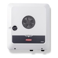
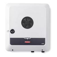
Fronius Primo 7.6-1 208-240 User Manual

Fronius Primo 7.6-1 208-240
58 pages
To Next Page IconTo Next Page
Page #1 background imageLoading...
Page #1 background image
/ Perfect Charging / Perfect Welding / Solar Energy
Fronius Primo 208-240
3.8-1 / 5.0-1 / 6.0-1
7.6-1 / 8.2-1
10.0-1 / 11.4-1
12.5-1 / 15.0-1
Operating Instructions
Inverter for grid-connected photo-
voltaic systems
Instructions de service
Onduleur pour installations photo-
voltaïques connectées au réseau
Manual de instrucciones
Inversores para instalaciones foto-
voltaicas acopladas a la red
EN-USFR
ES
www.youtube.com/FroniusSolar
LEARN MORE WITH
OUR HOW-TO VIDEOS
42,0410,2116 014-15122015

Table of Contents

Other manuals for Fronius Primo 7.6-1 208-240

Questions and Answers:

Fronius Primo 7.6-1 208-240 Specifications

General IconGeneral
Power Output7.6 kW
Protection ClassIP65
Frequency60 Hz
Max. apparent AC power7.6 kVA
AC nominal voltage208 V / 240 V
MPP voltage range200-800 V
AC Voltage Range183-264 V
MPPT Range200-800 V
Operating Temperature Range-25°C to +60°C
Warranty10 years

Summary

Introduction

Explanation of Safety Instructions

Explains safety symbols like DANGER, WARNING, CAUTION, NOTE, IMPORTANT.

Safety Rules

General

Arc Detector / Interrupter

Describes the integrated arc detection and interruption feature.

Warning Notices Affixed to the Device

Details on warning labels and symbols present on the device.

String Fuses

Information on using string fuses for solar module protection.

Criteria for the Proper Selection of String Fuses

Guidelines for selecting appropriate string fuses.

RGM – Optional Revenue Grade Meter

Data Communication and Solar Net

Fronius Solar Net and Data Interface

Explains Solar Net for linking inverters and system add-ons.

System Monitoring

Starting for the First Time via the Fronius Solar.web App

Guide to setting up the Fronius Data Manager 2.0 using the Solar.web App.

Keys and Symbols

Keys and Symbols

Identifies and describes the function of physical keys and status LEDs.

Display

Explains the inverter’s display interface and modes.

Menu Level

Accessing the Menu Level

Step-by-step guide to navigating the inverter's menu system.

Menu Items NOW, LOG, and GRAPH

NOW

Displays real-time values of the inverter.

LOG

Logs data for the current day, year, and since first use.

GRAPH

Graphically represents output power over time.

Values Displayed in the Menu Items NOW and LOG

Lists data shown in the NOW and LOG menu items.

The SETUP Menu Item

Navigation in the SETUP Menu Item

How to navigate and access items within the SETUP menu.

General Setup Menu Item Settings

How to adjust settings for various menu items.

Application Example: Setting the Feed-In Tariff

A practical example of setting the feed-in tariff in the SETUP menu.

The Setup Menu Item

Standby

How to manually activate/deactivate standby mode and restore grid feed.

WiFi Access Point

Procedures for activating/deactivating the WiFi Access Point.

DATCOM

Inverter Number

Setting the unique address for each inverter in a system.

USB

Software Update

Steps for updating inverter software using a USB stick.

Arc Detection

ArcDetector Status/Start Self-test

Checking the status of arc detection and running a self-test.

The INFO Menu Item

Switching the Key Lock On and Off

Switching the Key Lock On and Off

Step-by-step guide to activating/deactivating the key lock function.

USB Stick as a Data Logger and for Updating Inverter Software

USB Stick for Updating Inverter Software

Using a USB stick to update the inverter's software.

The Basic Menu

General

Overview of important parameters set in the Basic menu.

Accessing the Basic Menu

Procedure to access and navigate the Basic menu.

Status Diagnosis and Troubleshooting

Technical Data

Terms and Conditions of Warranty and Disposal

Related product manuals