Do you have a question about the Fronius Primo 208-240 and is the answer not in the manual?
Explains DANGER, WARNING, CAUTION, NOTE, and IMPORTANT symbols for safety.
Explains symbols for indoor, outdoor, and direct sunlight installation suitability.
Illustrates and describes acceptable vertical, horizontal, and inclined mounting positions.
Shows and explains incorrect mounting orientations, like upside down or with sockets facing up.
Details further incorrect orientations like overhanging or ceiling mounting.
Defines the purpose of the inverter and emphasizes proper usage guidelines.
Specifies environmental conditions, clearances, and surface requirements for installation.
Details environmental and clearance requirements for larger inverter models.
Explains selection of mounting hardware and recommends specific screw types.
Provides instructions and diagrams for attaching the wall bracket to the mounting surface.
Details mounting the inverter on a mast using a specific kit and compatible mast diameters.
Describes the purpose and sizes of knockouts for various wiring entries.
Provides instructions and safety precautions for removing knockouts using tools.
Details methods for removing rear knockouts and attaching appropriate conduits.
Lists the compatible electrical grid configurations (voltage, frequency, phases) for the inverter.
Specifies allowed cable types, materials, and sizes for AC and DC connections.
Details special procedures for connecting aluminum cables due to their non-conducting oxide layer.
Outlines steps for cleaning and greasing aluminum cable ends for secure connection.
Emphasizes the importance of low resistance in leads for optimal grid monitoring.
Provides instructions for grounding, cable looping, and ground conductor routing for AC connection.
Lists maximum AC fuse ratings for different inverter models to ensure safety.
Advises on the need for external disconnects in accessible installations for safety personnel.
Advises on selecting modules, checking open circuit voltage, and module grounding.
Warns against grounding solar modules and improper DC cable routing to prevent damage.
Details connecting multiple solar strings to the inverter's independent MPP trackers.
Explains how to configure the inverter for single MPP tracker operation, including bridging.
Describes connecting a single string to the inverter, including necessary bridging of inputs.
Details connecting multiple strings to the larger Fronius Primo 10.0-15.0 models.
Specifies rules for installing data communication cables, including conduits, openings, and routing.
Details how to securely clip and lock the inverter onto the wall bracket, including the safety lock function.
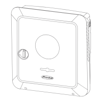
Explains the installation procedure for the optional anti-theft device before mounting.
Describes fitting a padlock to the installed anti-theft device for security.
Outlines the steps for updating the inverter software using a USB stick via the setup menu.
Explains how the USB stick logs data and how it can be accessed in various file formats.
Lists the system, log, and CSV files generated by the data logger on the USB stick.
Details storage capacity, file limits, and backup recommendations for USB sticks.
Explains the inverter's buffer memory for temporary data storage when the USB stick is removed.
Recommends compatible USB sticks and supported file systems for reliable operation.
Explains using the USB stick to transfer software updates to the inverter via the setup menu.
Details the correct procedure to remove the USB stick to prevent data loss or corruption.
Advises on checking screws for tightness annually for certain installation types.
Provides instructions for cleaning the inverter and display using a damp cloth.
Explains where to find the inverter's serial number on the rating plate.
Describes how to use and apply the provided serial number stickers for easy identification.
| Output Power | 3.8 kW |
|---|---|
| Protection Class | IP65 |
| THD | < 3 % |
| AC grid frequency | 60 Hz |
| AC nominal voltage | 208/240 V |
| AC voltage range | 183-264 V |
| Operating Temperature Range | -25°C to +60°C |
| Warranty | 10 years |
| Max. output current | 16 A |