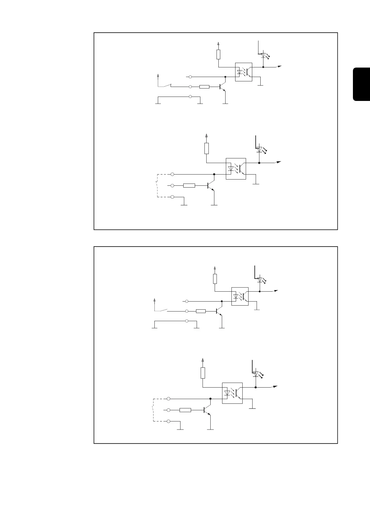
Version 1:
external 24 V
activation
Version 2:
Potential-free
(Terminal 1/3)
(Terminal 1/11)
+ 24 V from the automatic-
welder control system
V
DC
(internal)
max. 100 V
GND external GND input GND input
GND uP
uP
V
DC
(internal)
(Terminal 1/10)
(Terminal 1/11)
max. 100 V
uP
GND uP
GND inputGND input
Terminal 1/3 ....... HI-Roboter ready / Quick-Stop
Terminal 1/11 ..... GND-Roboter ready / Quick-Stop
Terminal 1/10 .... LO-Roboter ready / Quick-Stop
Terminal 1/11 .... GND-Roboter ready / Quick-Stop
Automatic welder
Power source
(3)
(3)
Making the power source ready for welding
Version 2:
Potential-free
(Terminal 1/4 bzw. 1/5)
(Terminal 2/13 bzw. 2/
14)
+ 24 V from the automatic-
welder control system
V
DC
(internal)
max. 100 V
GND external GND input GND input
GND uP
uP
V
DC
(internal)
(Terminal 1/12 or 1/6)
(Terminal 2/13 or 2/14)
max. 100 V
uP
GND uP
GND inputGND input
Terminal 1/4 ...... HI-Job BIT 0
Terminal 1/5 ...... HI-Job BIT 1
Terminal 2/13 .... GND-Job BIT 0
Terminal 2/14 .... GND-Job BIT 1
Terminal 1/12 .... LO-Job BIT 0
Terminal 1/6 ...... LO-Job BIT 1
Terminal 2/13 .... GND-Job BIT 0
Terminal 2/14 .... GND-Job BIT 1
Version 1:
external 24 V
activation
Automatic-welder
Power soource
(4) or (5)
(4) or (5)
Initialising Bit 0 and 1 for job-retrieval
25
EN