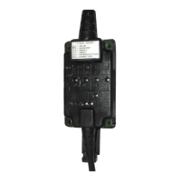
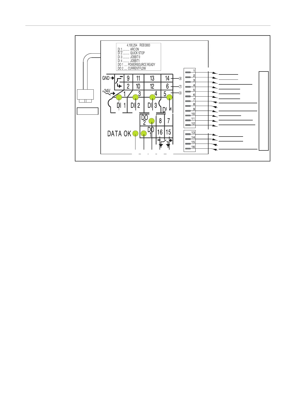
Indicators and
connections of
the automatic-
welder interface
ROB 3000
ROB 3000
Plug LocalNet
Power source
Automatic-welder control system
Terminal1
HI - ARC ON
LO - ARC ON
HI - ROBOTER READY
HI - JOB BIT 0
HI - JOB BIT 1
LO - JOB BIT 1
CURRENT FLOW SIGNAL
GND - ARC ON
LO - ROBOTER READY
GND - ROBOTER READY
LO - JOB BIT 0
GND - JOB BIT 0
GND - JOB BIT 1
POWER SOURCE READY
SUPPLY POWER SOURCE
READY
SUPPLY CURRENT FLOW
SIGNAL
Lamp-wire connectors
Terminal2
(2) (3) (4) (5)
(1) (9) (10) (12) (11)
(1) DATA OK indicator ... lights up when the ROB 3000 is connected to the Local-
Net and the power source is switched on
(6) Digital inputs (HI), on Terminal 1, with external 24 V activation
Important! Instead of the inputs (6), it is also possible to use the potential-free
inputs (7).
(7) Potential-free digital inputs (LO), on Terminal 1
(8) Earth (GND) for the high-active digital inputs (6), or for the potential-free
inputs, on Terminals 1 and 2
(11) Digital outputs, on Terminals 1 and 2
(12) Connections for signal voltage supply of the digital outputs, on Terminals 1
and 2
24