115
EN-US
Key: Primary = DC (DC+ and DC-) | Secondary = AC (L and N) | Ground = PE
The insulation resistance test must be conducted between the following points on both the
inverter and the wall bracket.
However, on the DC disconnector the measurement should only be taken on the screws
and not on the contacts.
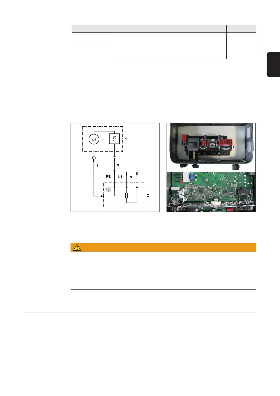
1 Measuring instrument
2 Inverter
9 Measuring line
Examples for measuring the insulation resistance
WARNING!
An electric shock can be fatal. Capacitors can charge during the insulation resis-
tance measurement.
After carrying out the insulation resistance test, check that all tested potentials are de-en-
ergized before continuing with the safety inspection. Alternatively, the capacitors can be
discharged by short-circuiting the tested potentials or via the discharge function on the in-
sulation tester.
Capacitor discharge time is at least 5 minutes.
Ground Conduc-
tor Discharge
- Measurement should only be carried out once the insulation resistance test has been
passed.
- Mount the inverter lid again.
- Only successful measurement between the lid and wall bracket guarantees that the
ground conductor function of the inverter is working.
- Ensure the device to be checked has been securely disconnected from the AC grid
(grid power line [L and N] must not be connected). If the AC grid cannot be disconnect-
ed from the wall bracket, the appropriate safety precautions must be taken.
- Re-insert the inverter in the wall bracket.
Measurement Test voltage Limit value
Primary ->
Ground
at least the max. DC input voltage of the device, how-
ever max. 1000 V
>= 1 M
Secondary ->
Ground
>= 500 V >= 1 M
Ground to AC / Ground to DC
 Loading...


