88
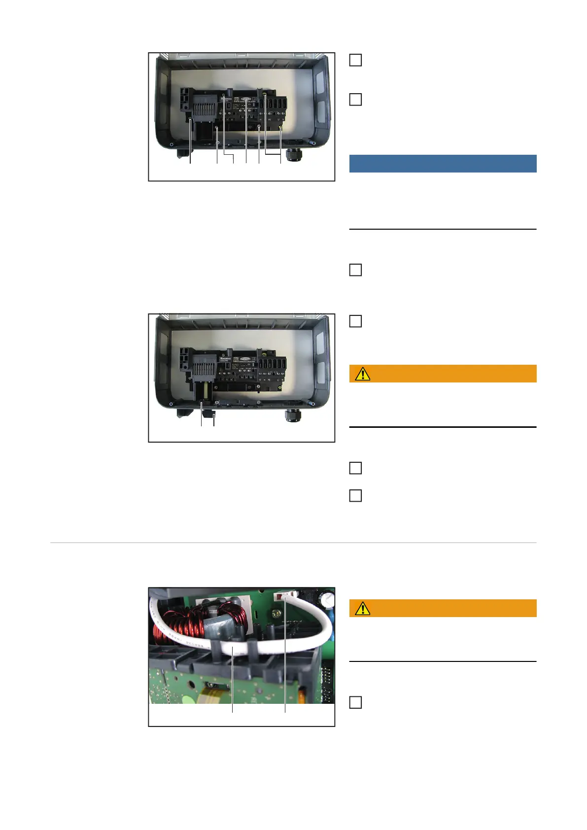
Refit the hidden fuse (5) removed pre-
viously
Insert the new DC disconnector and
mount using four 4x9 TX20 screws (4)
[2 Nm]
NOTE!
If the two left PE contacts (5) of the ter-
minal block are not required, tighten the-
se to 1.6 Nm.
Mount the strain-relief device using two
4x20 TX20 screws (3)
[3–4 revolutions]
Insert the control switch and shaft (2)
and secure it with the retaining clip (1)
WARNING!
Take safety precautions.
Observe the safety rules – DC voltage pre-
sent!
Connect the AC and DC lines to the
terminal block of the DC disconnector
Place the inverter in the wall bracket
(see "Opening and Closing the De-
vice")
Replacing the 4k5
External Fan
Removing the External Fan:
WARNING!
Follow the safety rules (see the begin-
ning of the "Safety" section)
Take the inverter out of the wall bra-
cket and open it (see "Opening and
Closing the Device")
(3)(3)(4) (4) (4)(5)
1
2
3
(2)
(1)
3
5
6
(2)
(1)
1
 Loading...


