Do you have a question about the Fronius TPS 2700 MV and is the answer not in the manual?
Details the main parts of the welding system: torch, wirefeeder, power source, gas, and cooling unit.
Illustrates the arrangement of weld system components and their connections.
Describes different ways to set up the weld system with various wire feeder placements.
Details features of TPS 2700, TS 3200/4000/5000, and TPS 3200/4000/5000 power sources.
Details features of TsT 3500 Compact, Manual, and Robotic power source models.
Explains the identification, technical details, and serial number age determination on the nameplate.
Provides detailed technical specifications for TPS, TS, and CMT-A power source models.
Details front panel, power, and communication connections for TPS 3200/4000/5000.
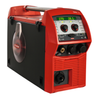
Details front panel and basic, optional, and auxiliary connections for TPS 2700.
Details front panel and basic, optional connections for TsT 3500/5000.
Details front panel, basic, and specialized connections for TsT Compact.
Details VR 1500, VR 1550, VR 4000, and VR 7000 CMT wire feeder models.
Details VR 1500 PAP, VR 5000 Manual, and VR 5000 ROB wire feeder models.
Shows the drive rolls, tension knobs, wire guide insert, and main drive roll.
Illustrates different types of torch connectors used with wire feeders.
Details welder and torch connections, and control buttons for the VR 1500.
Details welder/torch connections and control features for the VR 7000.
Lists and describes manual and robotic welding torch types.
Lists standard features and specific FK 4000/5000 and FK 9000 cooler models.
Explains Shielded Metal Arc Welding (SMAW), Gas Tungsten Arc Welding (GTAW), and Gas Metal Arc Welding (GMAW).
Details Short Circuit, Globular, and Spray transfer modes in MIG welding.
Explains pulsed welding (GMAW-P) and notes concerning synergic welding.
Details characteristics of inert and active gases used in welding.
Compares active gases based on penetration, pores, stability, and spatter.
Explains the impact of CO2 concentration on the welding arc.
Details gas flow principles, rules of thumb, and Fronius options.
Explains the impact of neutral, push, and drag travel angles on welding.
Identifies and explains common weld discontinuities and their potential causes.
Step-by-step guide for initial setup, parameter selection, and starting welding.
Details correction values for MIG welding processes, divided into two sets.
Explains front panel controls for operation, selection, and adjustment.
Explains power, system status, parameter, and process-specific indicators.
Guides on selecting synergic lines and checking welding system software.
Guides on how to program and edit welding jobs.
Step-by-step procedure for resistance test and associated error codes.
Step-by-step procedure for push-pull alignment, including notes.
Lists PPU numbers for torches and explains PPU error codes.
Step-by-step procedure to verify cooler operation and flow switch notes.
Procedures for motor draw and output voltage tests.
Details MIG parameters, arc length correction, inductance, job storage, and feeder roll settings.
Provides navigation instructions and parameter lists for MMA (Stick) setup.
Explains indicators and controls for the TsT front panel in manual mode.
Explains indicators and controls for the TsT front panel in synergic mode.
Describes standard, knurled, professional, and synthetic drive rolls.
Describes specialty (Teflon, Graphite) and steel liners.
Explains contact tip quality, bore size, wire size, and thread size.
Illustrates torch components for no-drive, whip-drive, and CMT systems.
Provides tools and steps for liner installation.
Lists feeder rolls for various systems and misc. wire feeder/cooler consumables.
Lists consumables for AL 4000/AW 5000, AL 5000, AL 3000/AW 4000, and MTG 5300 S torches.
Lists consumables for MTG 4000 and Robacta 5000 robotic torches.
Lists PullMig, Robacta Drive, and CMT Robacta consumables and basic kits.
Describes Discrete I/O, Fieldbus, and Ethernet interface models for robots.
Explains interface role in system communication, connectivity, and control methods.
Lists major digital inputs/outputs and welding mode signals.
Maps welding modes to signal bit configurations for system control.
Overview of the Fronius Xplorer software and its general features.
Details backup, restore, connectivity display, license management, and options menu.
Explains Job tab for managing jobs and Docu tab for monitoring weld parameters.
Discusses factors affecting weld quality and systematic troubleshooting checks.
Explains various welder error codes related to power, circuits, and temperature.
Covers torch error codes, physical clues, consumable checks, and settings.
Explains wire feeder error codes related to logic, motors, communication, and encoders.
| Welding Process | MIG/MAG, TIG, MMA |
|---|---|
| Output Current | 270 A |
| Rated Input Frequency | 50/60 Hz |
| Maximum Output Current (MIG/MAG) | 270 A |
| Maximum Output Current (TIG) | 270 A |
| Maximum Output Current (MMA) | 270 A |
| Protection Class | IP 23 |
| Type | Inverter |
| Rated Input Voltage | 400 V |
| Cooling | Fan |