C
Crystal MartinAug 12, 2025
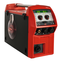
What to do if there is no welding current in my Fronius TPS 600i?
- PperezgabrielAug 12, 2025
If your Fronius Welding System shows no welding current, first, check the grounding connection and terminal for correct polarity. If the grounding is correct, the issue might be a break in the current cable within the welding torch, requiring you to replace the welding torch.