EasyManua.ls Logo

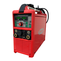
Fronius TransTig 1600 User Manual

Fronius TransTig 1600
58 pages
To Next Page IconTo Next Page
Page #1 background imageLoading...
Page #1 background image
TransTig 1600
TransTig 1700
42,0426,0023,EN 012006
Operating Instructions
Spare Parts List
TIG power source
GB
42,0426,0023,EN 003-08112013

Other manuals for Fronius TransTig 1600

Questions and Answers:

Fronius TransTig 1600 Specifications

General IconGeneral
BrandFronius
ModelTransTig 1600
CategoryWelding System
LanguageEnglish

Summary

Introduction

Welcome Message

Manufacturer's welcome, congratulations, and encouragement to read the manual.

Safety Rules

Safety Signal Words

Definitions of DANGER!, WARNING!, CAUTION!, NOTE!, and Important! safety signal words.

General Safety Remarks

Equipment built to state of the art; operator qualifications and manual adherence are key.

Usage Guidelines

Intended Purpose

Machine must only be used for defined welding processes and applications.

Ambient Conditions

Defines operating temperature, humidity, and air quality requirements.

Owner/Operator Obligations

Ensuring qualified personnel, understanding manual, and adhering to safety rules.

Personnel and Electrical Safety

Personnel Obligations

Requirements for personnel to be qualified, understand manual, and confirm adherence.

Mains Connection Safety

Guidelines for safe mains connection and electrical safety precautions.

Personal Safety Precautions

Protection against hazards like sparks, arc radiation, fields, noise, and fumes.

Health and Environmental Hazards

Noise Emission Values

Information on the sound power level generated by the device.

Hazards from Gases and Vapors

Risks of welding fumes and gases, and necessary protective measures.

Physical and Electrical Hazards

Hazards from Flying Sparks

Fire and explosion risks from sparks and safety measures to prevent them.

Hazards from Mains and Welding Current

Electrical shock risks from power sources and welding current; safety measures.

Electrical Current Hazards

Stray Welding Currents

Risks and causes of stray currents and methods for prevention.

Electromagnetic Compatibility (EMC)

EMC Device Classifications

Categorization of devices based on electromagnetic compatibility standards.

EMC Measures

Actions to prevent or mitigate electromagnetic interference issues.

Specific Operational Dangers

EMI Precautions

Health considerations for electromagnetic fields and user precautions.

Particular Danger Spots

Identification of hazardous moving parts and pinch points on the machine.

Welding Process Factors

Factors Affecting Welding Results

Requirements for shielding gas quality for optimal welding outcomes.

Ancillary Equipment Safety

Shielding Gas Cylinder Safety

Dangers of gas cylinders and safe handling procedures.

Installation and Transport Safety

Guidelines for safe machine placement and transportation.

Operational Safety Precautions

Normal Operation Safety

Ensuring protective features are functional and not bypassed during operation.

Maintenance, Inspection, and Disposal

Preventive and Corrective Maintenance

Recommendations for machine upkeep and parts replacement.

Safety Inspection

Guidelines for periodic safety checks and calibration.

Disposal

Instructions for environmentally responsible equipment disposal.

Safety Markings

Explanation of CE and CSA markings on the equipment.

User Information

Data Security

User responsibility for factory setting data security.

Copyright

Copyright notice and disclaimer for the instruction manual.

General Details

Basic System Principle

Description of the welding machine's transistor-switched technology.

Construction Features

Details on the machine's housing, controls, and portability.

Functional Sequence

Explanation of the thermostatic cut-out system's operation.

Control Panel

TT 1700 Control Panel Overview

Diagram and identification of the front panel components.

Description of Functions

Detailed explanation of each control and indicator on the panel.

Connections and System Add-ons

Front Panel Connection Points

Details of torch and gas connections on the machine's front.

Rear Panel Connections

Identification of rear connections for mains and remote control.

TIG Torch Assembly

Central Burner Connection GWZ

Instructions for connecting TIG torches with central burner connection.

Fronius Central Torch Connection F

Instructions for connecting TIG torches with Fronius central connection.

Commissioning and Setup

Mains Connection

Guidelines for connecting the machine to the mains power supply.

Setup Instructions

Procedures for machine placement, cooling, and stability.

TIG Operating Modes

General Remarks on TIG Modes

Introduction to TIG operating modes and general usage notes.

2-Step Mode

Detailed explanation of the 2-step welding process and its functional sequence.

Special 2-Step Mode

Special 2-Step Mode Operation

Description of the special 2-step mode, primarily for tack welding.

4-Step Welding Modes

4-Step Mode (No Lowering)

Configuration and sequence for 4-step welding without intermediate current lowering.

4-Step Mode with Lowering

4-Step Mode (Intermediate Lowering)

Configuration and sequence for 4-step welding with intermediate current reduction.

Special 4-Step Variants

Special 4-Step Mode Variant I

Description of Variant I, enabling 4-step mode without double-pushbutton.

Advanced 4-Step Modes

Special 4-Step Modes Variants II-V

Details on variants II through V, using double-pushbutton function.

Program Level Operations

Accessing Program Levels

Procedure to navigate and access different program levels.

Presettings Level

Explanation of the Presettings level for parameter adjustment.

Service Menu P1

Description of the Service Menu Level P1 with test programs.

Codelock Functionality

Level Codelock P2

Procedure for activating, changing, and deactivating the electronic codelock.

TIG Welding with HF Ignition

Safety Precautions for HF TIG

Critical safety warnings specific to TIG welding with HF ignition.

HF TIG Startup Procedure

Steps for setting up and initiating TIG welding with HF ignition.

HF Arc Ignition Process

Detailed explanation of how to ignite the arc using high frequency.

TIG Welding with Contact Ignition

Safety Precautions for Contact Ignition

Critical safety warnings for TIG welding using contact ignition.

Contact Ignition Startup Procedure

Steps for setting up and initiating TIG welding with contact ignition.

Contact Arc Ignition Process

Detailed explanation of how to ignite the arc using contact method.

Manual Electrode Welding

Safety for Electrode Welding

Essential safety warnings for manual electrode welding operations.

Electrode Welding Startup

Procedure for setting up and starting manual electrode welding.

Remote Control Operations

General Remote Control Usage

Introduction to remote control units for setting welding parameters.

TR 50mc Pulsing Unit Operation

Details on using the TR 50mc remote control pulsing unit and its functions.

Pedal Control Unit

TR 52mc Pedal Unit Usage

Operation of the TR 52mc pedal unit for amperage control during welding.

Spot Welding Unit

TR 51mc Spot Welding Unit Operation

Instructions for using the TR 51mc unit for spot welding tasks.

TPmc Remote Control Unit

TPmc Unit Functions

Explanation of the functions of the TPmc workplace remote control unit.

Troubleshooting and Error Handling

Safety During Troubleshooting

Critical safety warnings before opening the machine for troubleshooting.

Displayed Service Codes

List and meaning of error codes reported by the TMS16 board.

Care, Maintenance, and Disposal

General Care Remarks

Basic guidelines for minimal care and maintenance of the power source.

Maintenance Schedule

Routine checks and cleaning procedures for machine upkeep at different intervals.

Disposal Guidelines

Instructions for environmentally responsible equipment disposal.

Technical Data

TransTig 1600 / 1700 Specifications

Detailed technical specifications for both TransTig models.

Transig 1600 Circuit Diagram

Electrical Schematic for Transig 1600

Detailed electrical schematic diagram for the Transig 1600 model.

Transtig 1700 Circuit Diagram

Electrical Schematic for Transtig 1700

Detailed electrical schematic diagram for the Transtig 1700 model.

Related product manuals