EasyManua.ls Logo

Fronius TransTig 4000 - User Manual

Fronius TransTig 4000
140 pages
To Next Page IconTo Next Page
Loading...
Fronius prints on elemental chlorine free paper (ECF) sourced from certified sustainable forests (FSC).
/ Perfect Charging / Perfect Welding / Solar Energy
42,0426,0027,EN 018-23022017
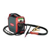
TransTig 2200
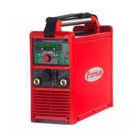
TransTig 2500 / 3000
TransTig 4000 / 5000
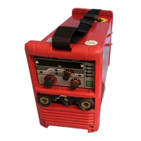
MagicWave 1700 / 2200
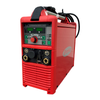
MagicWave 2500 / 3000
MagicWave 4000 / 5000
Operating Instructions
Spare parts list
TIG Power source
EN

Table of Contents

Questions and Answers:

Fronius TransTig 4000 Specifications

General IconGeneral
Input Voltage3 x 400 V
Output Current Range (MMA)10 - 400 A
Protection ClassIP 23
Mains Frequency50/60 Hz
Rated Input Frequency50/60 Hz
CoolingAir-cooled
Efficiency85%
Output Current Range (TIG)5 A - 400 A

Summary

Safety Rules

Explanation of Safety Symbols

Explains the meaning of hazard symbols used in the manual, such as DANGER, WARNING, and CAUTION.

General Safety Guidelines and Operator Obligations

Provides general safety guidelines, responsibilities, and qualifications for device operators.

Mains Connection and Personal Protection

Covers mains connection requirements and personal protection measures during operation, including clothing and ear protection.

Welding Hazards: Sparks, Electrical, Noise, Gases

Details risks from flying sparks, electrical shock, noise pollution, and toxic gases during welding operations.

Shielding Gas Cylinder and Installation Safety

Emphasizes safe handling of pressurized gas cylinders and precautions for device installation and transport.

Normal Operation and Maintenance Safety

Outlines safety measures for regular operation and essential safety precautions for maintenance procedures.

Control Elements and Connections

Control Panel Overview and Details

Provides an overview of control panels for MagicWave and TransTig, detailing their logical arrangement and elements.

Installation and Commissioning

Pre-Installation Safety and Setup Regulations

Covers safety checks, intended use, and setup regulations before device installation.

Start-up Procedures and Gas Cylinder Connection

Guides through start-up, cooling unit use, and safe connection of the gas cylinder.

Grounding and Welding Torch Connection

Details establishing ground connections to the workpiece and connecting the welding torch.

Welding

TIG Modes, Symbols, and Parameters

Explains TIG modes, their symbols, and key welding parameters like GPr, IS, I1, and downslope.

TIG Welding Operations: 2-Step and 4-Step Modes

Describes the operation sequences for the 2-step and 4-step TIG welding modes.

Troubleshooting and Maintenance

Related product manuals