Do you have a question about the Fronius TRANSTIG 330 and is the answer not in the manual?
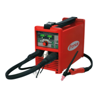
Describes the modular construction, compact dimensions, and quality features of the Fronius TRANSTIG welding machine.
Explains how cooling air circulates and details the machine's functional operational sequence.
Covers HF interference warnings and essential electrical work safety.
Provides key technical specifications and setup instructions for the welding machine.
Instructions for fitting mounting brackets, plates, and securing the power source.
Steps for inserting the cooling unit and connecting water hoses to the control unit.
Procedure for plugging the 5-pole power plug for the FK7 cooling unit into the power source.
Covers accessing the reservoir, checking water, and bleeding air from circulation.
Specifies using clean tap water and adding pure alcohol for frost protection.
Guidance on placing the gas cylinder on the platform and securing it with the safety chain.
Steps for preparing the gas cylinder valve and connecting the regulator and gas hose.
Details the Mains ON/OFF switch and operational readiness, over/undervoltage, and overtemperature indicators.
Explains the function selector switch and indicators for 2-step TIG welding.
Covers indicators and sequences for 4-step TIG welding variants.
Details the manual electrode welding indicator and the remote control unit socket.
Describes LED indicators for TIG pulsed arc and spot welding operations.
Covers gas pre-flow, start arc, up-slope, main current, down-slope, crater current, and post-flow.
Details the digital ammeter, HF selector switch, frequency range, and soft start dial.
Provides instructions for adjusting the spark gap and notes on ignition monitoring.
Steps for assembling a water-cooled TIG torch and connecting it to the machine.
Lists the different types of remote control units compatible with the machine.
Details the TP3 and TP4-SP remote control units for manual electrode and TIG welding.
Explains the function of the welding current and arc force control dials.
Covers the hot-start control dial and procedures for connecting remote control units.
Explains parameters used when no remote control unit is connected to the machine.
Discusses arc force range notes, switches, and their effects on welding characteristics.
Details connecting remote control units and welding without one.
Covers pulsing current dial, LED indicator, pulse frequency, and background current settings.
Explains the duty cycle dial and the toggle selector switch for operating modes.
Details connecting the TR 50-1 unit and its functional description.
How to regulate pulse current I, using the TR 52-1 remote-control pedal unit.
Procedure for linking the TR 50-1 pulsing unit to the TR 52-1 pedal unit.
Explains the machine's automatic switch to 2-step operation and pedal control functions.
Procedure for connecting the TR 52-1 unit and its functional description.
Explains the advantage of limited main current when using the remote pedal.
Procedure for connecting the TR 51 spot-welding unit and its functional description.
Instructions for starting TIG welding using high-frequency ignition.
Steps for setting up the machine for TIG welding with HF ignition.
Describes arc ignition using the FHF 5-1 device, including torch positioning.
Steps for setting up the machine for contact ignition TIG welding.
Steps for setting up the machine for soft-start contact ignition TIG welding.
Instructions for setting up the machine for manual electrode welding.
Covers machine safety, electrical hazards, HF, PE conductor, OCV, and rectifier safety.
Details safety gear, eye protection, protection for others, ventilation, and container welding.
Procedure for replacing the TC 3 electronic module, requiring trained personnel.
Covers general maintenance and specific checks for water-cooled machines.
Troubleshooting steps for power-on failures and unresponsive torch triggers.
Diagnosing issues related to the absence of welding current.
Troubleshooting intermittent arc breaks.
Troubleshooting issues with gas flow, arc ignition, and HF signal strength.
Diagnosing arc breaks in manual welding and current regulation problems.
Troubleshooting remote control unit function and digital ammeter display.
Diagnosing issues with gas post-flow and the FK7 cooling unit.
Details setting dials for striking current, hot-start, arc force, and welding current.
Explains the status of LEDs and displays for theoretical values on the RET 34 board.
Describes LEDs for transient protection and PWM start-up.
Indicates LEDs for mains overvoltage, phase fault, and voltage fluctuations.
Details LEDs for emergency stop, current flow, gas, HF, and torch triggers.
Covers voltage LEDs, the potential-free relay, and the %/Abs. slider switch.
| Brand | Fronius |
|---|---|
| Model | TRANSTIG 330 |
| Category | Welding System |
| Language | English |






 Loading...