75
DUTY CYCLE DIAL (%)
(Setting dial for pulse / interval relationship)
This dial is for setting the relationship, in percentage terms,
between the pulsing current phase and the background cur-
rent phase.
Setting-example 1
Duty cycle dial
is in scale position 10,
i.e. short pulsing current phase of 10 %, and long background
current phase of 90 % - means low degree of heat impact.
(Assuming that certain welding parameters are set).
Setting-example 2 (Fig. 29)
Duty cycle dial
is in scale position 50,
i.e. pulsing current phase and background current phase are
equally long (each 50 %) - means medium degree of heat
impact.
(Assuming no change in the welding parameters that are set).
Setting-example 3
Duty cycle dial
is in scale position 90,
i.e. long pulsing current phase of 90 %, and short background
current phase of 10 % - means high degree of heat impact.
(Assuming no change in the welding parameters that are set).
TOGGLE SELECTOR SWITCH I
1
INT/I
1
(remote control pedal unit)
Description of operating mode --> MANUAL regulation of
pulse current I
1
Connecting the remote control unit:
Link the connecting socket on the power source and the
remote-control unit socket electrically with the remote
control cable.
Plug in the plug-in connections the right way round, and screw
the coupling ring on as far as possible.
When a successful connection is made, the LED indicator ,
(for pulsed-arc welding) on the TC 3 control section of the
power source will light up.
Functional description:
Functional sequence only possible in 4-step operating mode
LED indicator symbol: lights up on the power source
Shift the toggle switch on the remote control unit into the I
1
INT. position.
Preselect the required frequency range on the front operating
panel of the machine (TC3), using the range switch
(0,25 - 5Hz / 5 - 100Hz / 100 - 2000Hz)
The pulsing current I
1
is set continuously (between "Min." and
"Max.") with setting dial
The setting for the background current I
2
is made as a percen-
tage of the pulsing current I
1
, with setting dial
To select the duty cycle (= the relationship of pulsing current I
1
to background current I
2
in %, the frequency remaining con-
stant), use dial
Set the pulse frequency dial to the desired value.
The pulse cycle is displayed by LED control lamps and
The parameters for gas pre-flow, start arc, up-slope, down-
slope, crater-fill current and gas post-flow are set directly at the
power source. In the 4-step operating mode, the pulse phase
begins as soon as the operator releases the torch trigger in the
up-slope. As can be seen in Fig. 30, pulsing also takes place in
the down-slope.
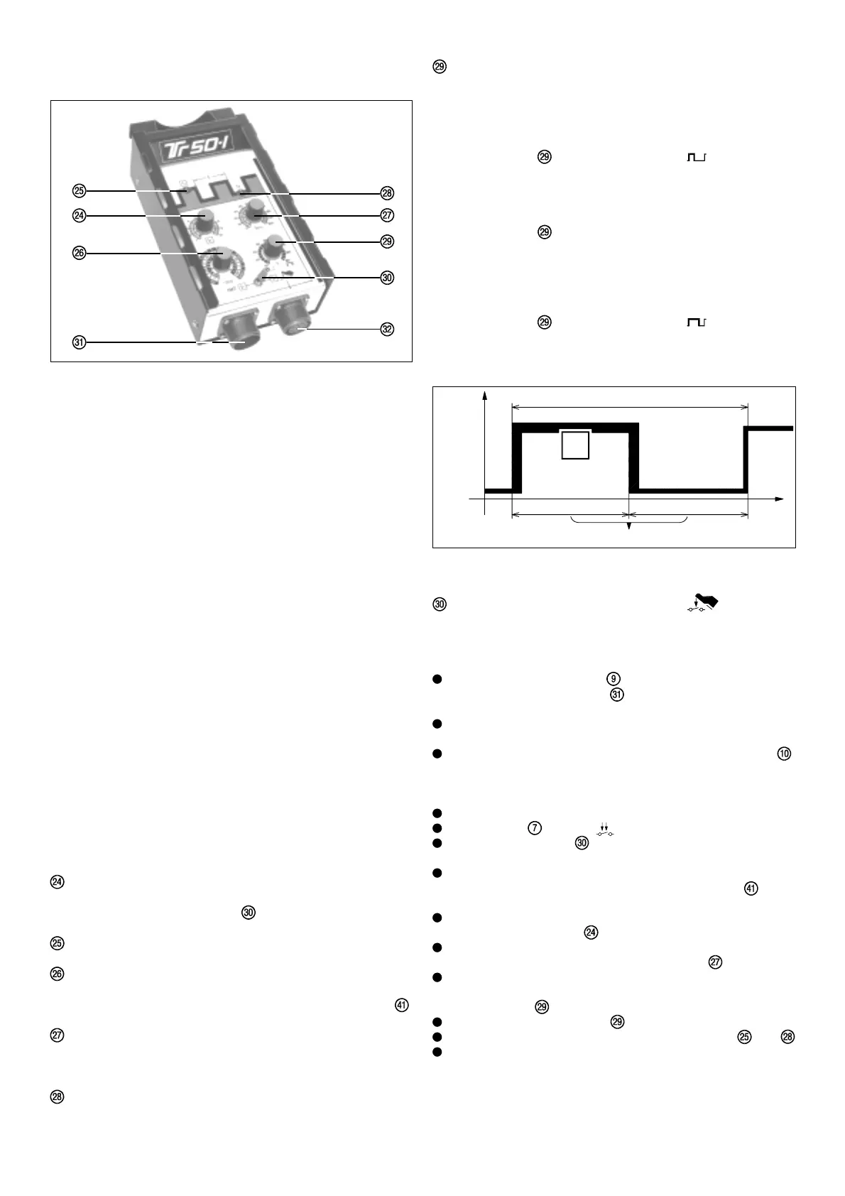
Fig. 28
COMMANDE A DISTANCE TIG PULSE
TR 50-1
Fig. 29
I
2
I
1
0
I
t
f
(Hz)
50%
50%
Duty-Cycle
Since a pre-set amperage is not always ideal for the entire
duration of a welding task, pulsating DC is often used. For
example, when welding pipes in cramped conditions, a change in
amperage is often necessary. Should temperatures rise too high,
there is a danger that liquid metal will begin to drop from the
welding pool. Too low, and the workpiece material will not melt
sufficiently.
Function: A relatively low welding current (background current I
2
)
rises via a steep up-slope to a considerably higher value (pulse
current I
1
) and drops again after a pre-set period (Duty-Cycle) to
the basic setting (background current I
2
), a process which repeats
itself over and over again. This is only possible when a specially
designed current source is used.
During the welding process, small sections of the weld zone melt
and solidify quickly. Welding a seam using this method is thus
considerably easier to control than if a large welding pool were to
form. This technique is also used when welding thin sheet metal.
Each fusion point overlaps the next, thus forming a neat and
regular seam. When the TIG pulsing technique is used when
welding by hand, the welding rod is applied at each current peak.
(Only possible in the lowest frequency range, i.e. 0,25 - 5 Hz).
Higher pulse frequencies are generally used in automatic welding
applications and serve mainly to stabilize the welding arc.
With the standard TR 50-1 remote control pulsing unit two oper-
ational modes are possible:
1. Regulation of impulse current I
1
by MANUAL operation of the
TR 50-1 remote control unit. (INT.)
2. Adjustment of impulse current I
1
by means of the TR 52-1
remote control pedal unit.
PULSING CURRENT DIAL I
1
(main current)
For continuous adjustment of the pulsing / main current in the
3 - 330 A range (toggle switch is on "INT").
LED INDICATOR for PULSING CURRENT I
1
PULSE FREQUENCY DIAL f (Hz)
For continuous adjustment of the pulse frequency, depending
on which frequency range has been preselected by switch .
BACKGROUND CURRENT DIAL I
2
The setting for the background current is made as a percen-
tage of the value set for the pulsing current I
1
LED-INDICATOR for BACKROUND CURRENT I
2