67
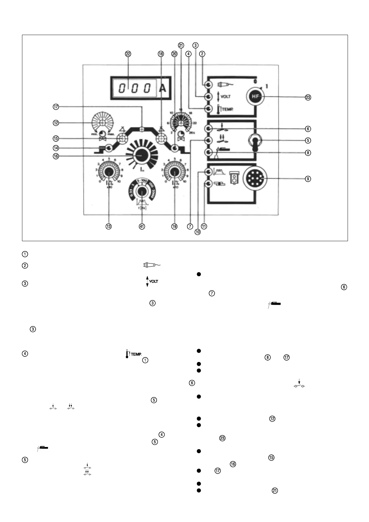
DESCRIPTION OF CONTROLS (valid for Transtig 330 and 450)
Mains ON/OFF switch (Fig. 19)
OPERATIONAL READINESS INDICATOR
lights up when the mains switch is shifted to "1"
OVER AND UNDERVOLTAGE INDICATOR
If the mains voltage rises/falls outside the +/-10% tolerance
range (Fig. 6), the voltage monitoring feature automatically
switches the machine off and the LED indicator
lights up
and stays on. In the event of momentary system voltage dips
or over-shoots, the power source will briefly cut out and then
immediately switch on again. In this case, the LED indicator
lights up for a period of 10 seconds.
If the mains voltage is within the given tolerance range, the
over and undervoltage indicator ought not to light up.
OVERTEMPERATURE INDICATOR
This lights up when the mains master switch is ON and:
a) the machine is overloaded and/or a temperature of 82° C
has been reached on one the primary or secondary heat
dissipators (see Fig. 2); or:
b) on water-cooled machines, where the power-plug for the
cooling unit is not plugged in to the 5-pole FK7 socket at the
rear of the machine. Function selector switch
is set to
TIG
or .
c) the cooling-unit plug FK7 is plugged into the back of a water-
cooled machine, but the cooling unit itself is faulty
(see Troubleshooting Guide p. 53 pt. 4).
IMPORTANT: The overtemperature indicator
goes
out as soon as the function selector switch
is set to
, even if Pts. b) and c) above apply.
FUNCTION SELECTOR SWITCH for
a) 2-step operation
} = TIG-welding
b) 4-step operation
If either of these two switch positions is selected, the machine
automatically switches over to the constant-current characte-
ristic necessary for TIG welding (= soft arc).
This puts the arc force control and hot-start devices out of
action (they may also no longer be influenced via the TP3 /
TP4-SP remote control unit).
When the TR 50-1, TR 51 or TR 52-1 remote-control units
are used, the system switches over to the operating mode
in question automatically - the respective LED indicators
or light up.
c) Manual electrode welding
When this switch position is selected, the welding characteri-
stics are governed by the mean values for ARC FORCE and
HOT-START which are fixed in the machine itself. It is only
possible to influence these parameters from outside via the
TP3 / TP4-SP remote control unit.(See description of TP3 /
TP4-SP remote control unit on p. 42-44)
After the required operating mode has been selected, the
respective LED indicator
and will light up.
FK7 cooling unit switches off automatically
Up / downslope function is inoperative
LED indicator for 2-step operation
called up via TIG torch trigger
used mainly for tack welding
Functional sequence:
1.Pull back the torch trigger and hold it down
Gas pre-flow time elapses
The arc ignites at start-arc current value I
s
either with or
without HF, depending on the position of the HF selector
switch
(N.B. HF switches off automatically following arc
ignition).
After the ignition process, the welding current rises via the
preselected up-slope (dial ) to the welding current I
H
set
on the dial
.
LED lights up.
2.Release torch trigger
Arc goes out (with or without current drop)
Gas post-flow time elapses
Fig. 15