35
ASSEMBLY OF WATER-COOLED MACHINES
If, for transport reasons or because specially requested by the
customer, the machine was delivered "knocked down", then
please proceed as follows when putting the machine into service:
Fit the mounting bracket and down onto the trolley frame
in such a way that the recesses and of both mounting
brackets are at the top left (Fig.7)
Insert the fastening plates (complete with ready-mounted
cage nuts) from the rear, as shown in Fig. 7, and screw them
on (loosely at first) using M8x20 steel screws fitted with
washers and retaining rings.
Place the power source on the mounting brackets and
and fasten from below using four M8 x 16 steel screws
compl. with washers and retaining rings.
Now screw both mounting brackets firmly to the trolley frame.
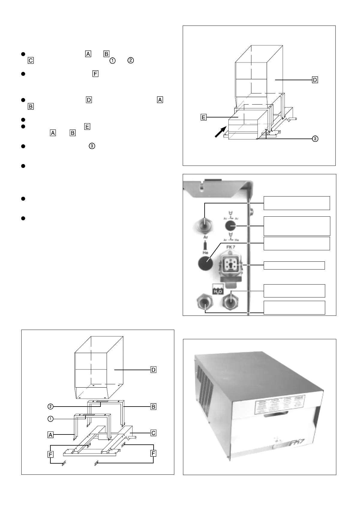
Insert the cooling unit from the front, through mounting
brackets
and , and position carefully.
(Insert the rear guide plate underneath).
As shown in Fig. 8, Point is the only point which needs to
be fastened (M8 x 16 steel screw from underneath, compl. with
washer and retaining ring).
Screw the threaded connectors for the water hoses onto the
water-connection points of the control unit in accordance with
the colour coding (blue = forward flow, red = return flow) and
tighten the knurled nuts by hand.
(First check that O-ring seals have been fitted).
Insert the plug-type connectors for the water hoses into the
water-connection points on the FK7 cooling unit in accordance
with the colour coding, and latch into place.
Insert the 5-pole power plug for the cooling unit into the
appropriate socket on the power source, the right way round,
and latch into place. Caution! 5-pole plug is only suitable for
FK7 cooling unit!
FK7 COOLING UNIT
Fig. 7 Fig. 10 Front view
Selector switch for autom.
inert gas switch over
after ignition (option)
Shielding gas - screw-type
connection - ARGON
Shielding gas - screw-type
connection - HELIUM (option)
Electr. cooling unit supply
Screw-type connection for
WATER FORWARD FLOW
Screw-type connection for
WATER RETURN FLOW
Fig. 9 Transtig water-cooled; detailed rear view
Fig. 8