57
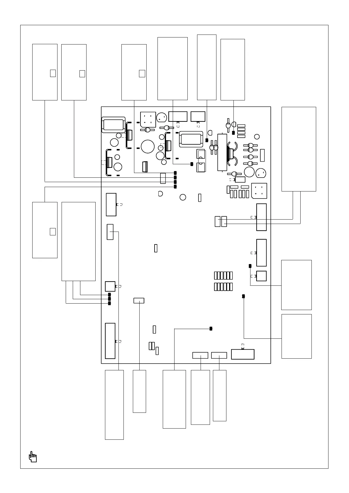
Fig. 51 LED checklist and description of setting-dials on RET 34. controller board
WARNING: Setting-dials not figuring above
may only be adjusted by Fronius personnel!
REMOTE CONTROL UNIT
LED indicator is lit up
when remote control unit
is activated
Setting dial for
HOT-START TIME
OPEN-CIRCUIT VOLTAGE -
STARTING SIGNAL
LED indicator goes out
3 secs. after current has
started to flow
LED indicator lights up when
OPEN-CIRCUIT VOLTAGE
is present
DES. VALUE FOR WELDING CURRENT
DES. VALUE FOR ARC FORCE
DES. VALUE FOR HOT-START
The higher the desired values,
the brighter the LED indicators.
Setting dial for
WELDING CURRENT Max. (300/450A)
WELDING CURRENT Min. (3A)
- is active in electrode and TIG
welding modes
CONTROLLER OUT
(Des. value for PWM).
The higher the desired
values, the brighter the
LED indicators.
LED indicator -15V
Must always be lit up when
the machine is ON -
otherwise F3 is faulty
LED indicator +5V
Must always be lit up when
the machine is ON -
otherwise F2 is faulty
LED indicator +10V
Must always be lit up when
the machine is ON -
otherwise F2 is faulty
Setting dial for
HOT-START CURRENT
(internal)
Setting dial for
ARC FORCE (internal)
PWM start-up
LED indicator lights
up as dictated by
current-flow
recognition
CURRENT FLOW SIGNAL:
LED indicator lights up when
welding current flow is
recognized
Setting-dial for striking-current,
10-30A; is only active for TIG
contact ignition without soft-start
LED indicator +15V
Must always be lit up
when the machine is ON -
otherwise F2 is faulty