46
Practical tips !
When FRONIUS welding torches with twin-function triggers are
used, the facility for lowering the current from main current to
crater-fill current and back again, without interrupting the welding
sequence, is available in the pulsed-arc operating mode as well.
For details of the functional sequence, see "Description of 4-step
operation / variant 2" (p. 38, Fig. 18).
Description of operating mode --> regulation of pulse
current I
1
using TR 52-1 remote-control pedal unit
A combination of the REMOTE CONTROL PULSING UNIT and
the REMOTE CONTROL PEDAL UNIT is particularly advantage-
ous with manual TIG welding in cases where it is necessary to
alter the welding pulse current during the welding operation.
(Where the welder is dealing with materials of different strengths,
for example).
Connecting the remote control unit:
Link the connecting socket on the power source and the
socket
on the remote-control pulsing unit electrically with
the remote control cable.
A remote control cable of the same type may be used for linking
the remote-control pulsing unit (socket
) to the remote con-
trol pedal unit (socket
).
Plug in the pug-in connections the right way round, and screw
the coupling ring on as far as possible.
When a successful connection is made, the LED indicator
(for pulsed-arc welding) on the TC 3 control section of the
power source will light up.
Functional description:
When the TR 52-1 remote-control pedal unit is connected, the
machine automatically switches over to 2-step operation.
LED indicator , symbol: (on the power source) lights up
Switch the tumbler switch on the TR 50-1 remote control
pulsing unit to the
position.
Gas pre-flow time and gas post-flow time are set directly at the
power source.
To initiate the ignition process, gently step on the pedal.
The level of the start arc current, the pulse current I
1
and the
final crater current can also be controlled from the pedal.
The base current I
2
that is set using the dial on the TR 50-1
is a constant percentage of the value of the pulse current I
1
.
When the welder takes his foot right off the pedal, the welding
current is switched off, thus interrupting the welding operation.
Gas post-flow time elapses.
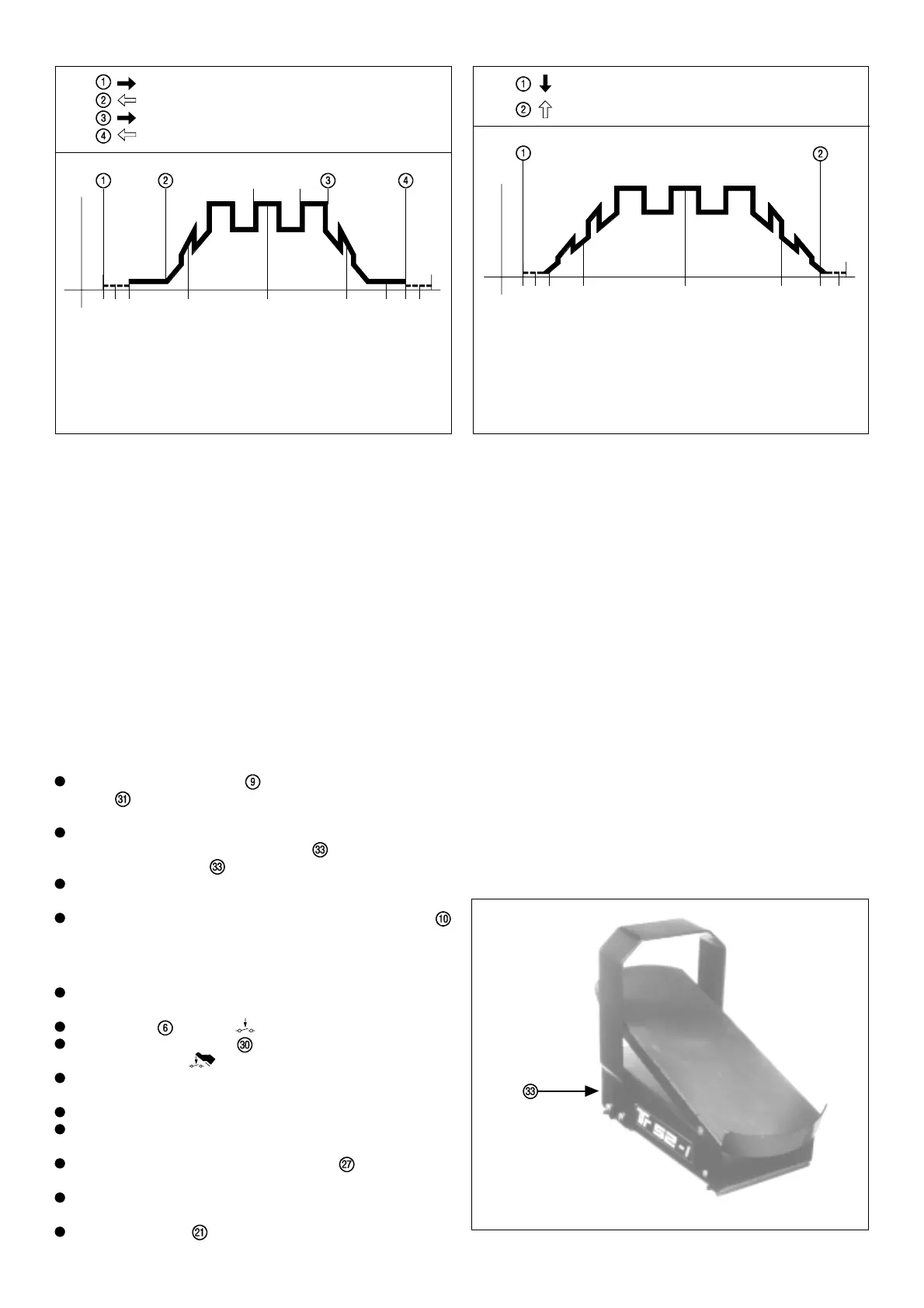
Pedal pressed down = welding "ON"
O
t
I
I
1
I
2
Start of cycle
Gas pre-flow time
Arc ignition with
minimum current
Pulsing current-rise
can be regulated by pedal
Pulsed-arc welding
operation I
1
- I
2
Pulsing current-drop
can be regulated by pedal
End of welding
Gas post-flow time
Pull back torch trigger and hold down
Release the torch trigger
Pull back and hold down the torch trigger once again
Release the torch trigger
Pulsing current-rise
via up-slope
Start of cycle
Gas pre-flow time
Arc ignition with start arc I
S
Pulsed-arc
welding operation
I
1
, I
2
/ f / Duty-Cycle
Current-drop (with pulse)
via down-slope
End of welding
Gas post-flow time
O
I
I
S
I
E
I
1
I
2
f(Hz)
t
Crater-fill current I
E
Fig. 31 Functional sequence in pulsed-arc operation, in conjunction with the
TR 52-1 remote-control pedal unit (2-step)
Fig. 30 Functional sequence in pulsed-arc welding operation using TR 50-1 (4-step)
Foot off the pedal = welding "OFF"
TR 52-1 REMOTE CONTROL PEDAL UNIT
Due to the fact that workpieces are often awkwardly shaped, it is
often necessary to alter the amperage in the course of the welding
operation. Typical cases are jobs such as repairing the edges of
tools, repairs or slight alterations in mould manufacture, or
improvements to cutting dies.
In this case, the edges must be kept intact when the arc is ignited.
However, when welding over thicker points, care must be taken
to ensure that no lacks of fusion occur. In addition to this, the
amount of heat created during the welding operation must be
carefully controlled, since if the seam is overheated, hardening
may occur, which may render any subsequent work considerably
more difficult.
These examples all demonstrate that, in such cases, the use of
a remote control pedal unit is indispensable.
Fig. 32