36
Fig. 14
Fig. 11 Rear view
Mains cable
2x400V / 50Hz
Plug-in connection for
water return-flow (red)
Plug-in connection for
water forward-flow (blue)
PUTTING THE COOLING UNIT INTO OPERATION
Open the twist-action lock and pull out the drawer containing
the coolant reservoir (see Fig. 13)
Undo the screw cap from the reservoir.
Before starting up the unit, always check the water level and the
quality of the water.
Top up with cooling water, up to the level of the water return-
flow opening.
ONLY USE CLEAN TAP WATER!
Add pure alcohol to the coolant, for both summer and winter
operation (see Table 1 for recommended mixing ratio).
The electrical conductivity of all other anti-freeze agents makes
them unsuitable for use here.
After switching the machine on (see "Start-up" on p. 48-50),
check the water circulation until water can be seen returning
unobstructed into the coolant container. If this does not occur,
bleed the air bubbles out of the forward-flow tubing:
How to bleed:
With the water pump running, pull back the retaining ring on
the blue plug-in connector (Fig. 11) and unplug the forward-
flow hose.
Using a wooden or plastic pin, briefly push in, and then release,
the conical nipple in the middle of the plug connector
(N.B. do not damage the sealing surface).
If no water comes out, repeat the procedure until all the air-
bubbles have been forced out and coolant is discharged when
the conical nipple is pushed in.
Plug the water forward-flow hose back in, and secure it.
Screw the cap back onto the coolant reservoir.
Push the drawer containing the coolant reservoir back in and
secure it with the twist-action lock.
Check that the water connections are watertight.
Mains voltage - pump motor
Current input
Speed
Protection
Cooling capacity
Throughput
Throughput pressure
Coolant volume
Dimensions (lxwxh)
Weight (not including coolant)
2x380V/400V/415V~ 50Hz
0,56 A
2800 R/min.
IP23
1,6 KW
5,2 l/min.
3,2 bar
ca. 5 l
575x365x265 mm
21 kg
TECHNICAL DATA
Mixing ratio
External temperature
Water Alcohol +° to -5°C -10°C
-15°C
-20°C
1,75 l
3,5 l 1,5 l
3,25 l
3,75 l 1,25 l
4,0 l
1,0 l
Table 1
Fig. 13
Topping-up opening
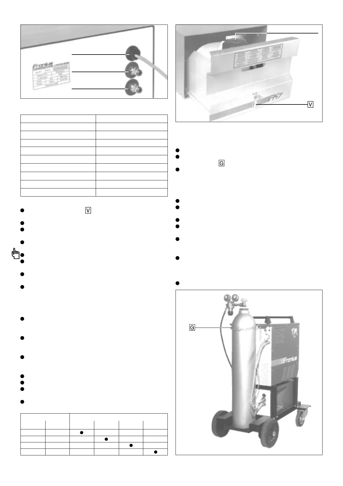
MOUNTING AND CONNECTING THE
SHIELDING-GAS CYLINDER:
Place the gas cylinder on the platform
Secure the cylinder to the rear of the machine by means of the
fastening chain
N.B.: To ensure adequate safety, the fastening chain must be
fixed around the upper third of the cylinder (but not around its
neck). If this is not possible, because the welding machine set-
up is not tall enough, e.g. at a gascooled unit, then - for safety
reasons - a smaller cylinder (e.g. 20 l) must be used.
Remove the protective cap from the gas cylinder
Give the cylinder valve a quick turn in an anticlockwise direction,
so that the gas jet removes any dirt which may have accumulated
Check the seal on the pressure regulator
Screw the pressure regulator onto the gas cylinder and tighten
using a 30 mm open-ended spanner
Screw the knurled nut of the gas hose onto the gas connection
on the power source, and tighten by hand (Fig. 14).
(N.B. first check that an O-ring seal has been inserted).
Connect the unit’s gas hose to the pressure regulator. Give the
thumb screw on the underside of the pressure regulator 2 to 4
turns in an anti-clockwise direction (this prevents damage to
the pressure regulator when the cylinder valve is opened)
Set the gas flow rate (see “TIG welding: Start-up” on p.48)
 Loading...


