34
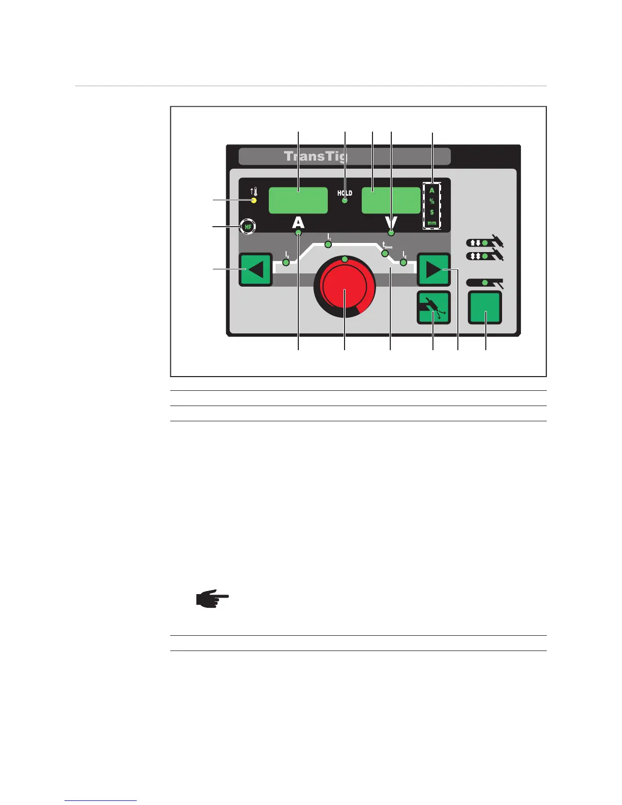
TransTig control panel
TransTig control
panel
No. Function
(1) Left digital display
(2) HOLD indicator
at the end of each welding operation, the actual values for the welding current and
voltage are stored and the Hold indicator lights up.
The Hold indicator refers to the last value reached by the main current I
1
. As soon
as any other welding parameter is selected, the Hold indicator goes off. The "Hold"
values will continue to be available, however, if welding parameter I
1
is selected
again.
The Hold indicator is cleared when:
- a new welding operation is started
- the welding current I
1
is set
- the mode is changed
- the process is changed
NOTE Hold values are not output if:
- the main current phase is never reached,
or
- a pedal remote control is used.
(3) Right digital display
(2)
(10)
(5)
(7)
(9) (8)
(3)
(11)
(1) (4)
(6)
(12)
(14)
(13)
 Loading...