33
EN
(12) Welding current indicator
for indicating the welding current for the welding parameters
- Starting current I
S
- Welding current I
1
- Final current I
E
Before welding commences, the left-hand digital display shows the set value. For
I
S
and I
E
, the right-hand digital display also shows the respective percentage of the
welding current I
1
.
After welding begins, the welding parameter I
1
is automatically selected. The left-
hand digital display shows the actual welding current value.
In the welding parameters overview (10), LEDs for the various parameters (I
S
, t
1
,
etc.) light up to show the relevant position in the welding process.
(13) Left parameter selection button
for selecting welding parameters within the welding parameters overview (10)
When a welding parameter is selected, the LED on the relevant parameter symbol
lights up.
(14) HF (high frequency) ignition indicator
lights up when the HFt set-up parameter has been set to an interval for the high fre-
quency pulses
(15) Overtemperature indicator
lights up if the power source overheats (e.g. because the duty cycle has been ex-
ceeded). See the "Troubleshooting" section for more information.
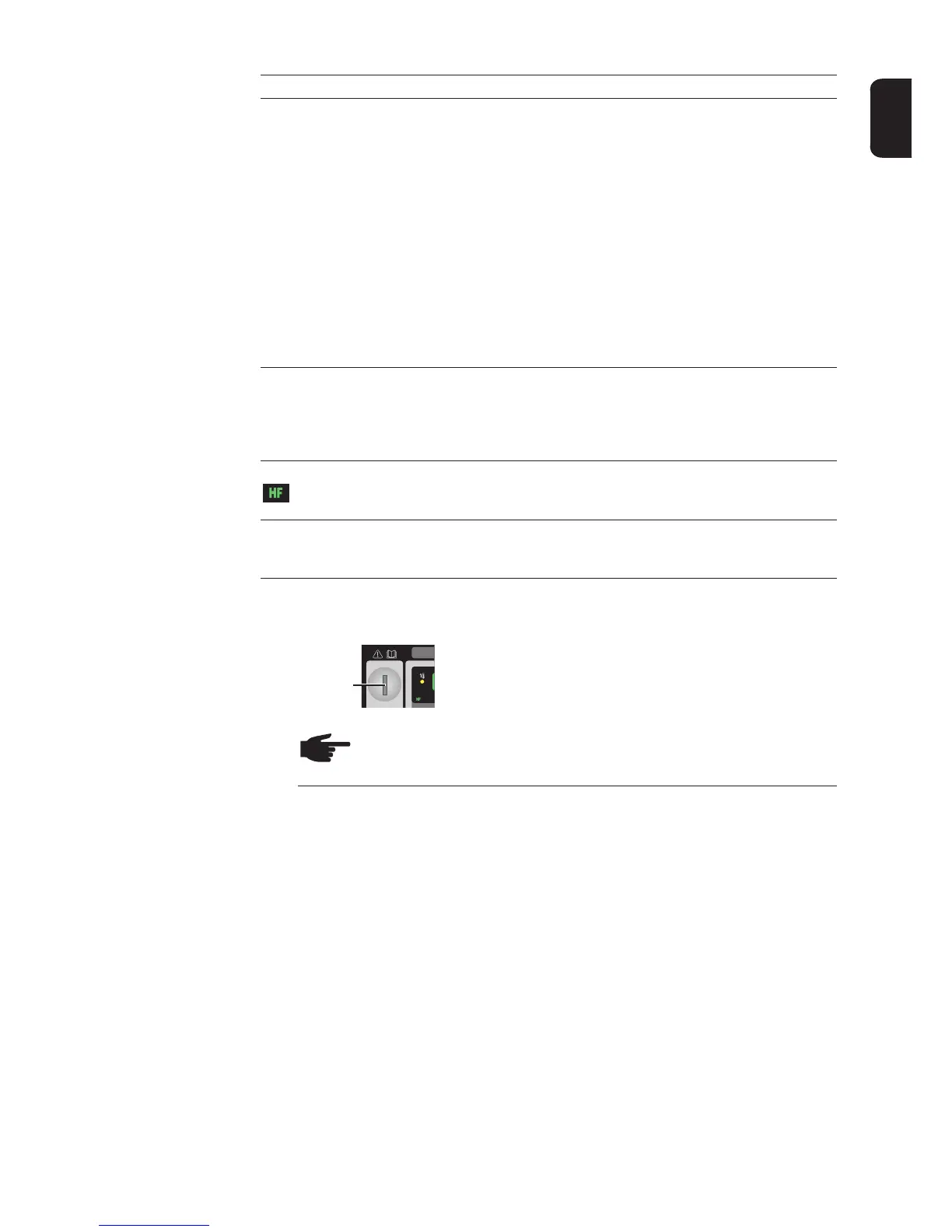
(16) Keylock switch (option for MW 2500 / 3000 / 4000 / 5000)
When the key is in the horizontal position, all parameters and functions are disabled
with the exception of the currently selected parameter or function.
(16)
Keylock switch position
NOTE The functions available on the control panel of system components
are restricted in the same way as those of the control panel on the power
source.
No. Function
 Loading...