51
EN
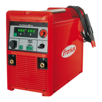
Insert the mains cable into the strain-
relief device
Tighten the clamping nut (size 30 mm)
Tighten the screws (2 x)
Connect the mains cable to the block
terminal correctly:
– PE conductor (green, or green
with yellow stripes) to the PE
connection
– Phase conductors to connections
L1 - L3
Replace the left side panel of the pow-
er source
Replacing the
strain-relief de-
vice
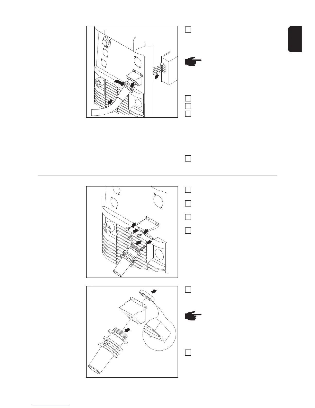
Remove the left side panel of the pow-
er source
Remove the screws (2 x) from the old
strain-relief device
Pull the old strain-relief device for-
wards to detach it
Remove the screws for the adapter
plate, and remove the adapter plate
Insert the hexagon nut (size 50 mm)
into the holding plate
Screw the front of the large strain-relief
device into the hexagon nut (size 50
mm). The hexagon nut (size 50 mm)
now bites into the holding plate.
PE
W1
V1
U1
5
7
8
6
NOTE! Push the mains cable in
far enough to make it possible to
connect the PE conductor and the
phase conductors to the block ter-
minal properly.
5
6
7
8
9
2
3
2
4
4
1
2
3
4
NOTE! The points of the hexagon
nut must point towards the holding
plate for a reliable ground (earth)
connection to the power source
housing.
5
6
 Loading...