35
EN
(4) Welding voltage indicator
lights up when parameter I
1
is selected. During welding the current actual value for the welding voltage is dis-
played on the right-hand digital display.
Before welding, the following appears on the right digital display:
- 0.0 if a TIG welding mode is selected
- 50 V if a MMA welding mode is selected (after a delay of 3 seconds; 50 V is the
average value for the pulsed open circuit voltage)
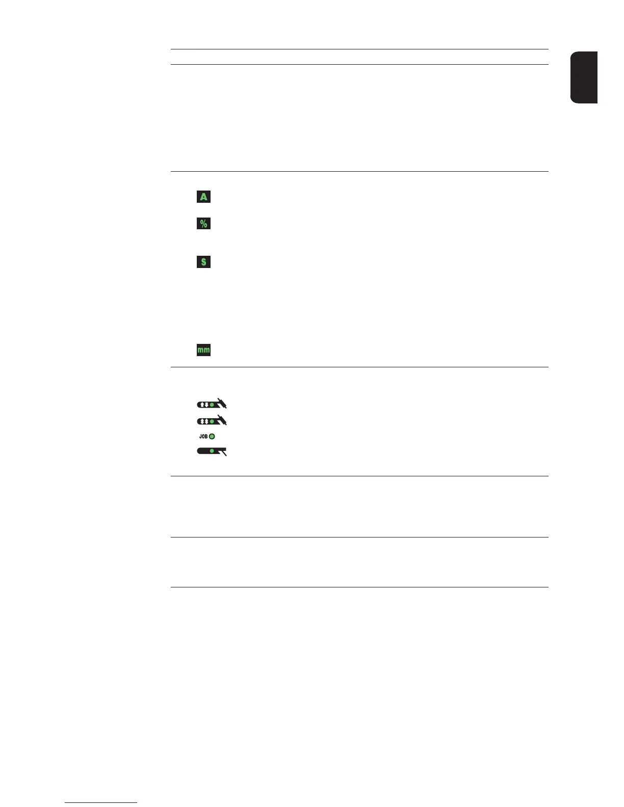
(5) Unit indicators
A indicator
% indicator
lights up when the I
S
, I
2
and I
E
welding parameters and the dcY, I-G and
HCU set-up parameters have been selected
s indicator
lights up when the t
up
and t
down
welding parameters plus the following set-
up parameters have been selected:
- GPr
- G-L
- G-H
- UPS
- tAC
- Hti
- HFt
mm indicator
lights up when the Fdb set-up parameter has been selected
(6) Mode button
for selecting the mode
2-step mode
4-step mode
Job mode
Manual metal arc welding
When a mode is selected, the LED on the relevant symbol lights up.
(7) Right parameter selection button
for selecting welding parameters within the welding parameters overview (10)
When a welding parameter is selected, the LED on the relevant parameter symbol
lights up.
(8) Gas test button
for setting the required shielding gas flow rate on the gas pressure regulator
After pressing this button, gas flows for 30 seconds. Press the button again to stop
the gas flow prematurely.
No. Function
 Loading...