18
4. If your configuration includes the TB14:
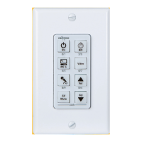
• If you are controlling a serial device (e.g., projector), connect the provided serial cable(s) to the TB14 adapter’s
RS232 captive screw connector. You can have up to two separate serial cables. Wiring is as follows:
• To control the first device:
• Black (ground) to Pin 3/GND
• Red (input to device) to Pin 2/TX1 OUT
• White (output from device) to Pin 1/RX1 IN
• To control a second device:
• Black (ground) to Pin 3/GND
• Red (input to device) to Pin 5/TX2 OUT
• White (output from device) to Pin 4/RX2 IN
IMPORTANT: Be sure to keep wiring and Action commands consistent to avoid
problems. For example, serial Actions sent to COM1 should use the TX1/RX1 pins;
actions sent to COM2 should use the TX2/RX2 pins. (See Appendix A.)
• If you are controlling a device via infrared (e.g., a DVD player), connect an IR emitter cable (not included; part
number 520-3001-001) to the TB14’s IR jack and secure the emitter end to the controlled device’s infrared sensor.
You can control up to two separate infrared devices. Be sure the CB2000 jumper (see page 2)
is set correctly.
• If you are using general purpose input (GPI) signals, be sure the CB2000 jumper (see page 2) is set correctly.
• Connect the power supply to the TB14 adapter
• Connect the Cat 5 cable to the AUX jack on the TB14 adapter
• If connecting your ezRoom to a local area network, connect the network cable to the “Network Only” jack
on the CB2000.
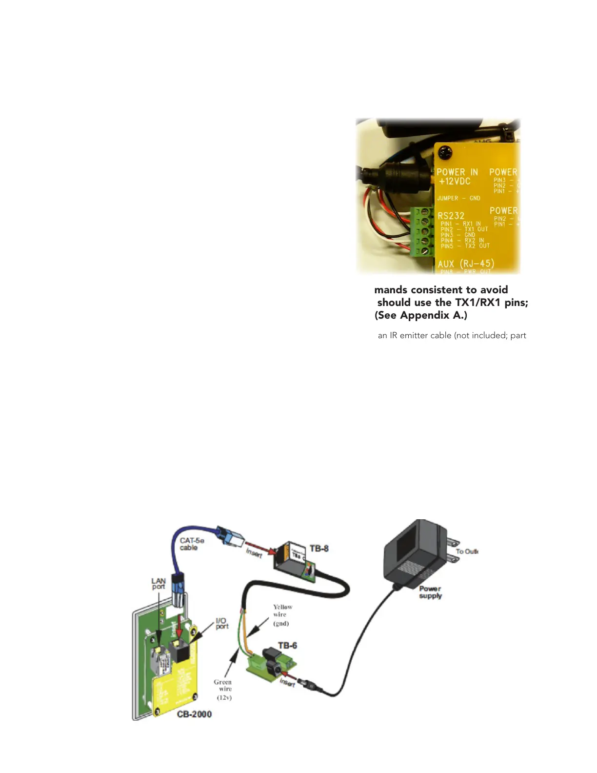
If your configuration includes the TB8 + TB6:
• Connect the CB2000 to the TB8 and TB6 as shown below.