Chapter 4: 15
4.1.12 The Breakout Board has:
The connector from the Chamber Board.
The Battery Pill, the White LED, the Speaker and both Telecoil jacks.
The Power/Status LED.
4.1.13 The Probe Board has:
The FPI connector from the Connector Board.
An RS232 interface between the FPI and the microcontroller.
A microcontroller that interfaces between the SBC and the circuits on this board.
Relays that direct the source signals to one of the speakers, the ER3, or to the
headphone jack.
Two probe microphone connectors, two instrumentation amps, a microphone
multiplexer, two prescale amplifiers, two probe equalizers, and two differential
line drivers.
An external keyboard connector and interface.
A Volume control and interface.
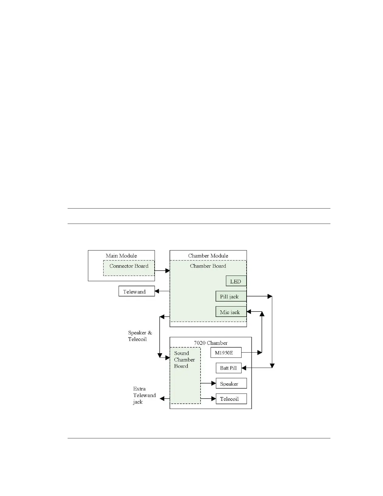
4.2 System Block Diagrams
4.2.1 8000 with 7020 chamber Partial System Block Diagram