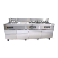
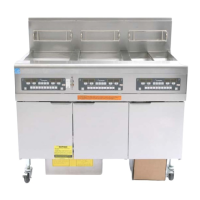
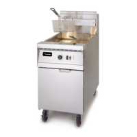
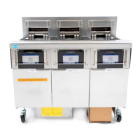
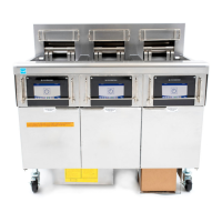
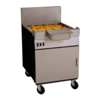
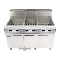
Frymaster 1814 Series Gas Fryers
Chapter 3: Installation
3-5
3.4 Gas Connections (cont.)
H. Flexible Couplings, Connectors and Casters: If the fryer is to be installed with flexible
couplings and/or quick-disconnect fittings, the installer must use a heavy-duty AGA design-
certified commercial flexible connector of at least ¾" NPT (with suitable strain relief), in
compliance with the Standard for Connectors for Movable Gas Appliances, ANSI Z21.69-
(latest edition) and Addenda Z21.69a-(latest edition). Quick disconnect devices must comply
with the Standard for Quick-Disconnect Devices for Use with Gas Fuel, ANSI Z21.41-(latest
edition).
1. For an appliance equipped with casters, the installation in the U.S. shall be made with a
connector that complies with Standard for Connectors for Movable Gas Appliances, ANSI
Z21.69-(latest edition) and Addenda Z21.69a-(latest edition). In the European Union, use a
flexible coupling certified as NF D 36123 (or other national standard) or a quick disconnect
device certified NF D 36124 (or other national standard). The coupling shall be periodically
examined and replaced as necessary.
WARNING
Do not attach accessories to this fryer unless fryer is secured from tipping. Personal
injury may result.
2. The fryer must be restrained by means independent of the flexible coupling or
connector in order to limit the movement of the fryer.
3. If disconnection of the restraint is necessary, this restraint must be reconnected after
the fryer has been returned to its originally installed position.
I. After hook-up, bleed the gas line of air to ensure that the pilot light will ignite quickly.
AUSTRALIAN REQUIREMENTS
To be installed in accordance with AS 5601, local authority, gas, electricity, and any other relevant
statutory regulations.
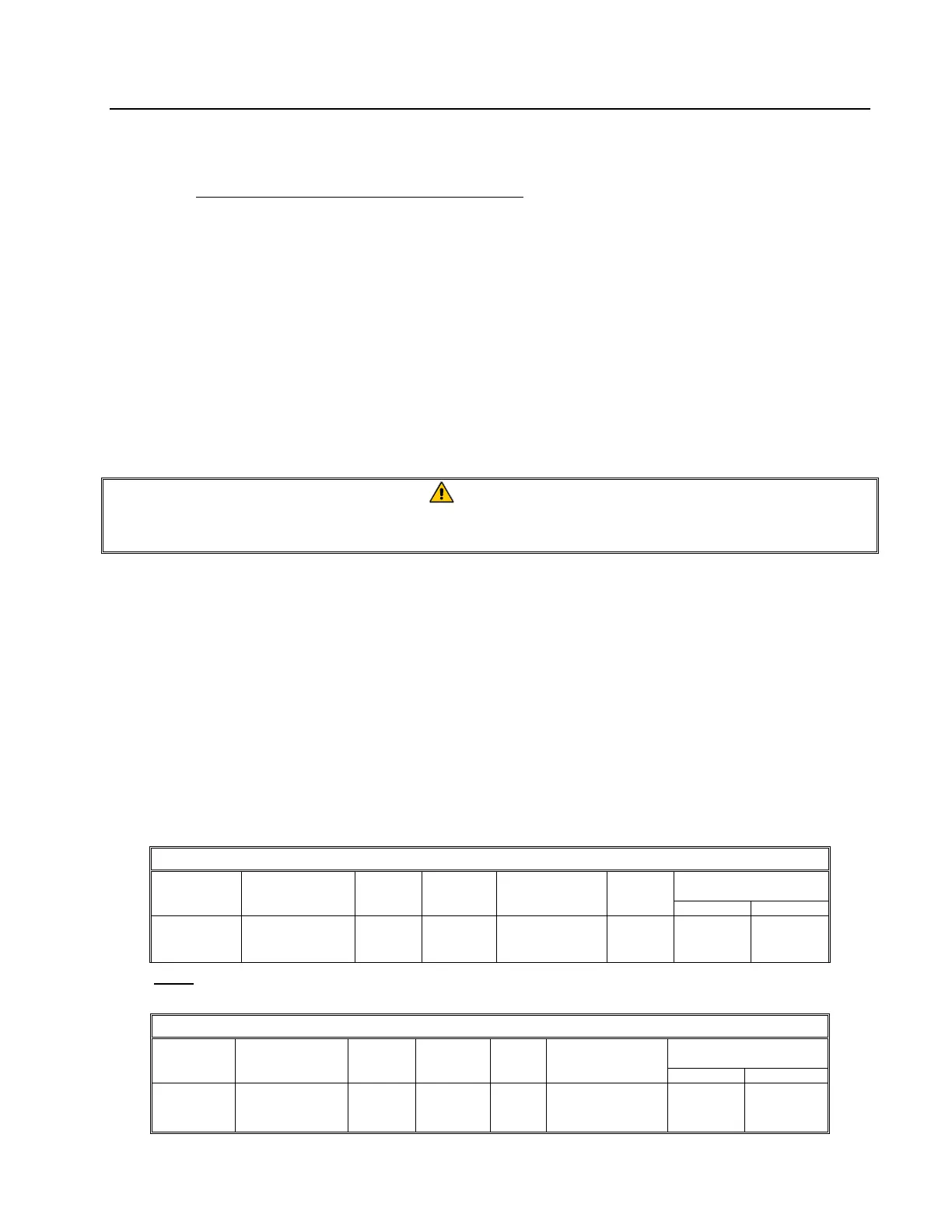
3.5 Gas Specifications
NON-CE
Altitudes of 2000 feet or less
MODEL
INPUT
(BTU)
GAS
TYPE
ORIFICE
(MM)
ORIFICE
PART NO.
QTY
EQUIPMENT
PRESSURE
MBAR INCH W.C.
1814 115
NAT
LP
2.26(#43)
1.40(#54)
810-2049
810-2324
5
5
10
27.5
4
11
NOTE: Outlet gas pressure must be adjusted strictly within the above requirements 5 to 10 minutes after the appliance is operating.
(Pilot Flame Adjustment: Turn the pilot adjustment screw clockwise/counter-clockwise until the desired flame-volume is achieved.)
CE ONLY
Altitudes of 2000 feet or less
MODEL
INPUT
(kW)
GAS
TYPE
ORIFICE
(MM)
QTY
PILOT ORIFICE
(MM)
EQUIPMENT
PRESSURE
MBAR INCH W.C.
1814 33,7
G20
G25
G31
2,2
2,2
1,4
5
5
5
.46
.46
.33
10,0
15,0
23,9
4,0
6,0
9,5