Innovation · Expertise · Agility
12
Hardware Installation and Parts Replacement
Switch Hardware Installation and Maintenance Guide
2. Lock
the
AC
power
cable
with
the
locking
strap.
3. Connect
the
other
end
of
the
AC
power
cable
to
the
external
AC
power
supply
system.
-
Perform
the
following
steps
to
connect
the
DC
power
cables:
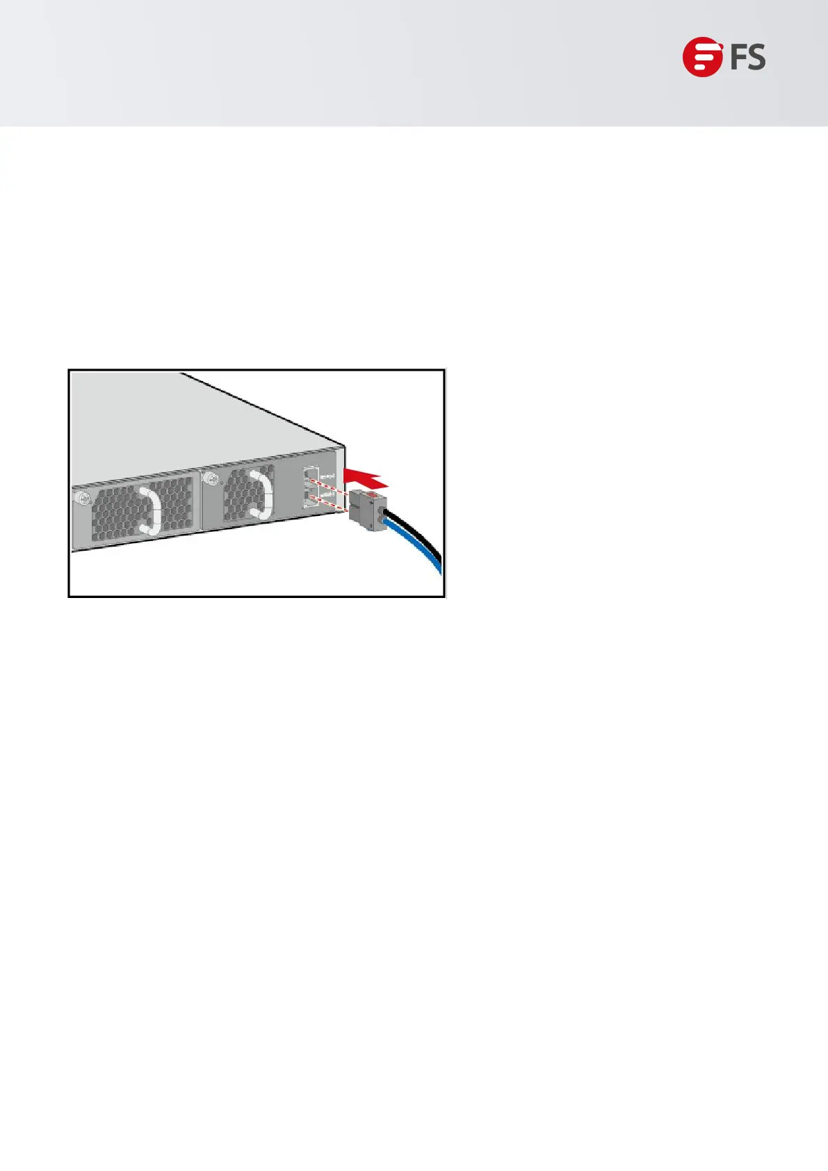
1. Insert
the
DC
power
cable
plug
to
the
power
socket
in
the
DC
power
module.
Ensure
that
the
positive
pole
of
the
plug
is
connected
to
the
positive
socket
and
the
negative
pole
is
connected
to
the
negative
socket
on
the
power
module.
Figure 7: Connect the DC Power Cable
2. Connect the cord end terminals at the other end of the power cables to the external DC power supply
system. Generally, cord end terminals of the power cables are connected to a DC power distribution box.
Connect the positive and negative power cables to the positive and negative terminals in the DC power
distribution box correctly.
1.5.2 Connecting Ethernet Cables
Connect the RJ45 connector of an Ethernet cable to the management port on the equipment, and the other
end to a network management switch or terminal.
1.5.3 Connecting Optical Fibers
Insert the single-mode or multi-mode fiber into the corresponding interface according to the panel
identification, and distinguish the transmit and receive ends of a fiber cable.
 Loading...