Innovation · Expertise · Agility
14
Hardware Installation and Parts Replacement
Switch Hardware Installation and Maintenance Guide
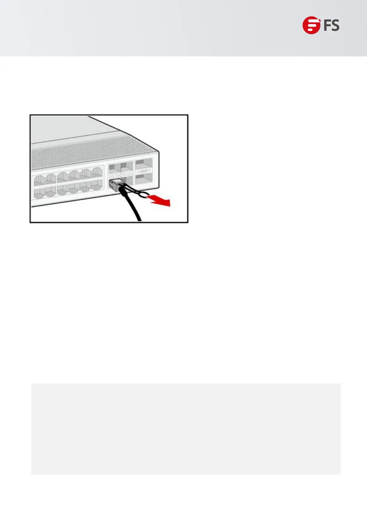
To remove a high-speed cable, gently push the cable connector and then pull the handle of the connector. Do
not directly pull the cable connector with force. See Figure 9.
Figure 9: Removing a High-speed Cable
6. Bundle high-speed cables. Arrange the high-speed cables to make them parallel, and then bundle them
with cable ties at an interval of 150mm to 300mm. Use diagonal pliers to cut off redundant cable ties.
7. Replace all the temporary labels with permanent labels on the high-speed cables.
1.5.5 Connecting the Grounding Cable
There is one ground terminal on the back of the N8560-48BC switch chassis, which should be connected to
the grounding lug of the rack first, and then connect the grounding lug to the grounding bar of the equipment
room.
Precautions:
• The sectional area of the grounding wire should be determined according to the possible maximum current.
Cables of good conductors should be used.
• Do not have bare wires exposed.
• Grounding resistance: Less than 1Ω.
• To guarantee the security of the person and the equipment, the switch must be grounded properly.
The grounding resistance between the chassis and the ground should be less than 1Ω.
• The maintenance personnel should check whether the AC socket is reliably connected to the
protective ground of the building. If not, the maintenance personnel should use a protective ground
conductor from the AC outlet protective ground terminal to the building protective ground.
• The power socket should be installed near the equipment and easily accessible.
• When installing the switch, connect the grounding first and disconnect it last.
• The cross-sectional area of the protection ground wire should be at least 2.5mm
2
(12AWG).
 Loading...