NANO PRO
6
5. Nano PRO Electrical Installation
The Nano PRO has a 12-way connector with 3 wire groups. One of them has the connector for the O2 sensor, the
second makes the CAN communication with Power FT ECU’s and the third is responsible for power and analog output.
By default, the analog output is set to values of 8.7AFR to 16.2AFR Gas, but can be congured to 5.1AFR to 17.6AFR
Gas or 9.6AFR to 19.1AFR or 9.6AFR to 58.8AFR or yet 9.6AFR to 146AFR (Gas), if necessary.
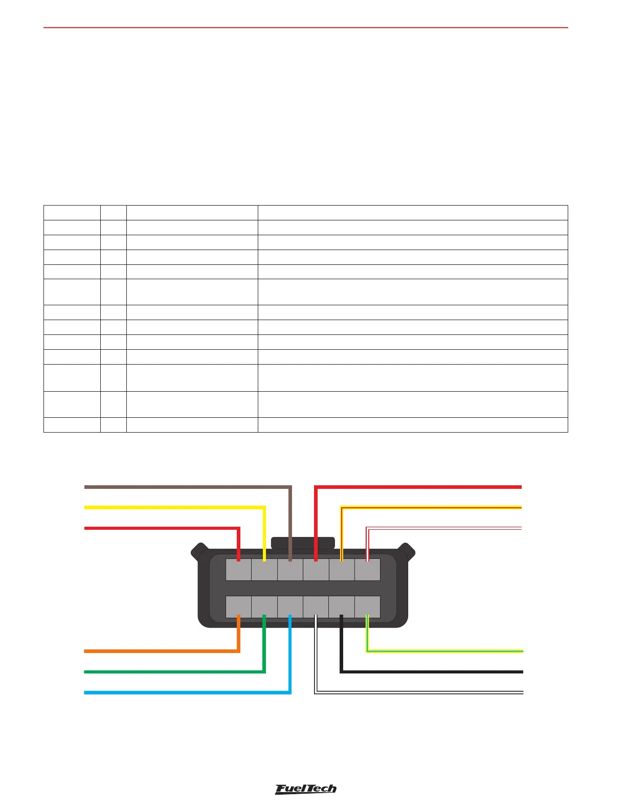
See the following wiring diagram for details about connections.
12-way connector
Wire color Pin Connection OBS to Connections
Red 1 O2 sensor O2 sensor pin 6 - IP
Yellow 2 O2 sensor O2 sensor pin 5 - sensor negative signal
Brown 3 O2 sensor O2 sensor pin1 - Sensor positive signal
Red 4 Switched 12V The use of a 10A fuse is recommended
Yellow/Red 5 0-5V Analog Output
Analog output proportional to the lambda readings. Used for connection
with data acquisition systems
White/Red 6 CAN CAN (+): connected to Power FT ECU’s CAN port
Orange 7 O2 sensor O2 sensor pin 2 - sensor resistor calibration
Green 8 O2 sensor O2 sensor pin 3 - sensor heater positive
Blue 9 O2 sensor O2 sensor pin 4 - Sensor heater negative signal
Black/
White
10
Chassis/Engine Power
Ground
Engine ground (head/block)
Do not connect it directly to the battery negative.
Black 11 Battery’s Negative
Connected directly to the battery negative with no splices. Do not connect
this wire to the chassis engine block or head.
Yellow/Blue 12 CAN CAN (-): connected to Power FT ECU’s CAN port
Power Ground - Black/White
Lambda Output - Yellow/Red
Switched 12V - Red
Battery Ground - Black
7 8 9 10 11 12
1 2 3 4 5 6
O2 sensor - Pin 6 - Red
O2 sensor - Pin 5 - Yellow
O2 sensor - Pin 1 - Brown
CAN HI - Pin 4 - White/Red
O2 sensor - Pin 4 - Blue
O2 sensor - Pin 3 - Green
O2 sensor - Pin 2 - Orange
CAN LOW - Pin 3 - Yellow/Blue
Harness Connector Rear View