FSC B17-1 Service Manual
10
4. Input/Outpt Specification
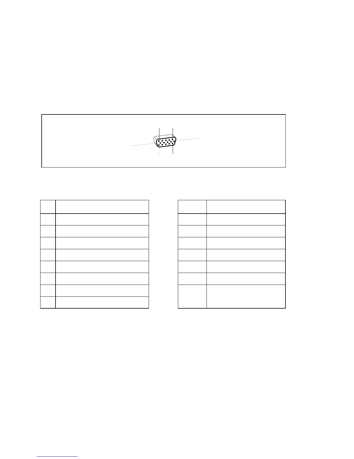
4.1 Input Signal Connector
4.1.1 Analog D-SUB Connector
1
5
6
10
11
15
Pin Meaning Pin Meaning
1 Video input red 9 +5 V (DDC)
2 Video input green 10 Sync. ground
3 Video input blue 11 Ground
4 Ground 12 DDC-Data
5 Ground 13 H. sync
6 Red video ground 14 V. sync
7 Green video ground 15 DDC Clock
8 Blue video ground
 Loading...