01-25
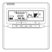
1-26. DESCRIPTION OF DISPLAY UNIT
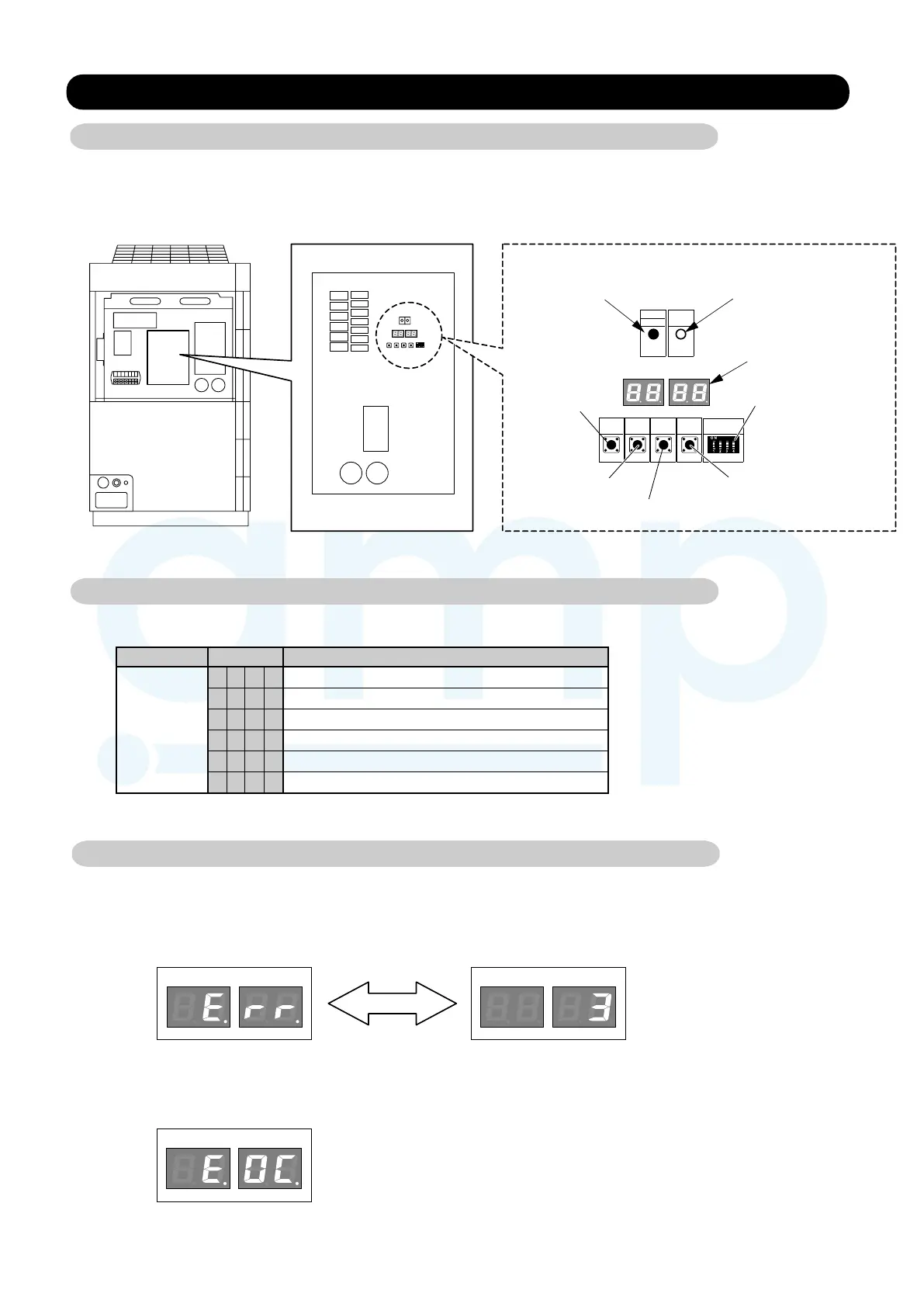
1-26-1 Field setting switches
Remove the front panel of the outdoor unit and the cover of the electrical component box to access
the print circuit board of the outdoor unit.
Print circuit board switches for various settings and LED displays are shown in the figure.
Outdoor unit printed circuit board
POWER
LED105 LED104
SW101
ERROR
MODE
LED101
(GREEN)
MODE
/EXIT
PUMP
DOWN
SELECT
ENTER
SW107
SW108
SW109 SW102
LED102
(RED)
7 Segment LED Lamp
(LED105 and LED104)
Status of the unit will display.
POWER/MODE Lamp (LED101)
It lights up when power on.
ERROR Lamp (LED102)
It will flash rapidly in case of an error.
MODE/EXIT button
(SW107)
PUMP DOWN button (SW102)
SELECT button (SW108)
ENTER button (SW109)
DIP switch (SW101)
Operation status is displayed in 7 Segment LED Lamp (LED105 and LED104).
Mode
CODE
DESCRIPTION
Operation
C L
H t
d F During defrosting operation
Cooling
Heating
P C During power saving operation
L n During low noise operation
Stopped
10.2.1. Method for ascertaining the errors
(1) When an error has occurred, ERROR LED (LED102) will flash rapidly, and as shown in the figure below,
7 Segment LED will alternately display "Err" and number of errors.
(2) Error contents will display if ENTER button (SW109) is pressed in the state of (1).
For error contents, refer to the list of error code described later.
LED105 LED104 LED105 LED104
Alternate display
Error display
Display number of errors
LED105 LED104
Ex.) "E.0C" is displayed.
Discharge temperature
thermistor error.
1-26-2 Normal operation mode
1-26-3 Error display mode
www.ampair.co.uk | sales@ampair.co.uk