64 Operating Manual TX300 S7 / RX350 S7
Starting up and operation
6.2 Controls and indicators
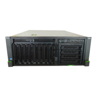
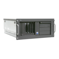
6.2.1 Front of server
Figure 8: Front of server (example: rack model)
I The meaning of the local diagnostic indicators (1) - (6) is described in the
"PRIMERGY TX300 S7⁄ RX350 S7 Server Upgrade and Maintenance
manual".
1 HDD/SSD error indicator 11 Power-on indicator
2 PSU error indicator 12 On/Off button
3 Temperature error indicator 13 NMI button
4 CPU error indicator 14 Reset button
5 Memory error indicator 15 ID button
6 Fan error indicator 16 USB connector
7 ID indicator 17 USB connector
8 CSS indicator 18 Front management LAN
connector (optional)
9 Global Error indicator 19 Optional Front VGA
10 HDD/SSD activity indicator
?@A
0
6
5
4
3
2
1 98
7
:
;<=>
 Loading...