5. INSTALLING THE REMOTE CONTROLLER
5.1. Wiring
WARNING
Before starting installation work, turn off the power of the connection
destination. Do not turn on the power again until installation is completed.
Otherwise, it will cause electric shock or re.
Use the accessories or specied connection cables.
Do not modify connection cables other than those specied, do not use
extension cords, and do not use independent branch wiring. The allow-
able current will be exceeded and cause electric shock or re.
Install the connection cables securely to the terminal block. Conrm that
external force is not applied to the wire. Use connection cables made
of the specied wire. If intermediate connection or insertion xing are
imperfect, it will cause electric shock, re, etc.
Do not connect functional earthing to a telephone functional earthing,
water pipe, or conductor rod.
Always fasten the outside covering of the connection cable with the cable
clamp. (If the insulator is chafed, electric leakage may occur.)
When performing cable wiring work, be sure that it does not touch the
user. Doing so will cause injury or electric shock.
If any cable is damaged, do not repair or modify it yourself. Improper work
will cause electric shock or re.
CAUTION
Do not parallel to the remote controller cables, indoor and outdoor
connection cable, and power supply cables. It may cause erroneous
operation.
When performing wiring work, be careful not to damage the cable or
injure yourself. Also, connect the connectors securely. Loose connectors
will cause trouble, heating, re, or electric shock.
Install the remote control cable 3ft. (1 m) away from television and radio
to avoid distorted images and noise.
Perform wiring so that water does not enter this unit along the external
wiring. Always install a trap to the wiring or take other countermeasures.
Otherwise it will cause trouble or electric shock or re.
Conrm the name of each unit and name of each terminal block of the
unit and connect the wiring in accordance with the directions given in the
manual so that there is no incorrect wiring. Incorrect wiring will damage
the electric parts and cause smoke and re.
When installing the connection cable near a source of electromagnetic
waves, use shielded cable. Otherwise, a breakdown or malfunction could
result.
5.2. Connection of remote controller cable
CAUTION
When connecting the remote controller cable to the wall mounted type
and the oor type indoor unit, do not connect it to the outdoor unit or the
indoor unit power terminal block. It may cause a failure.
There are 2 methods to connect the remote controller cable to the indoor
unit. One is the connection using contained connecting cable and the other
is the connection the remote controller cable is connected to the exclusive
terminal block of the indoor unit.
Exclusive terminal block for remote controller connection method is different
depending on each model. Modify the remote controller cable as per below
description and connect it.
(For the details, refer to the installation manual of the indoor unit to be used.)
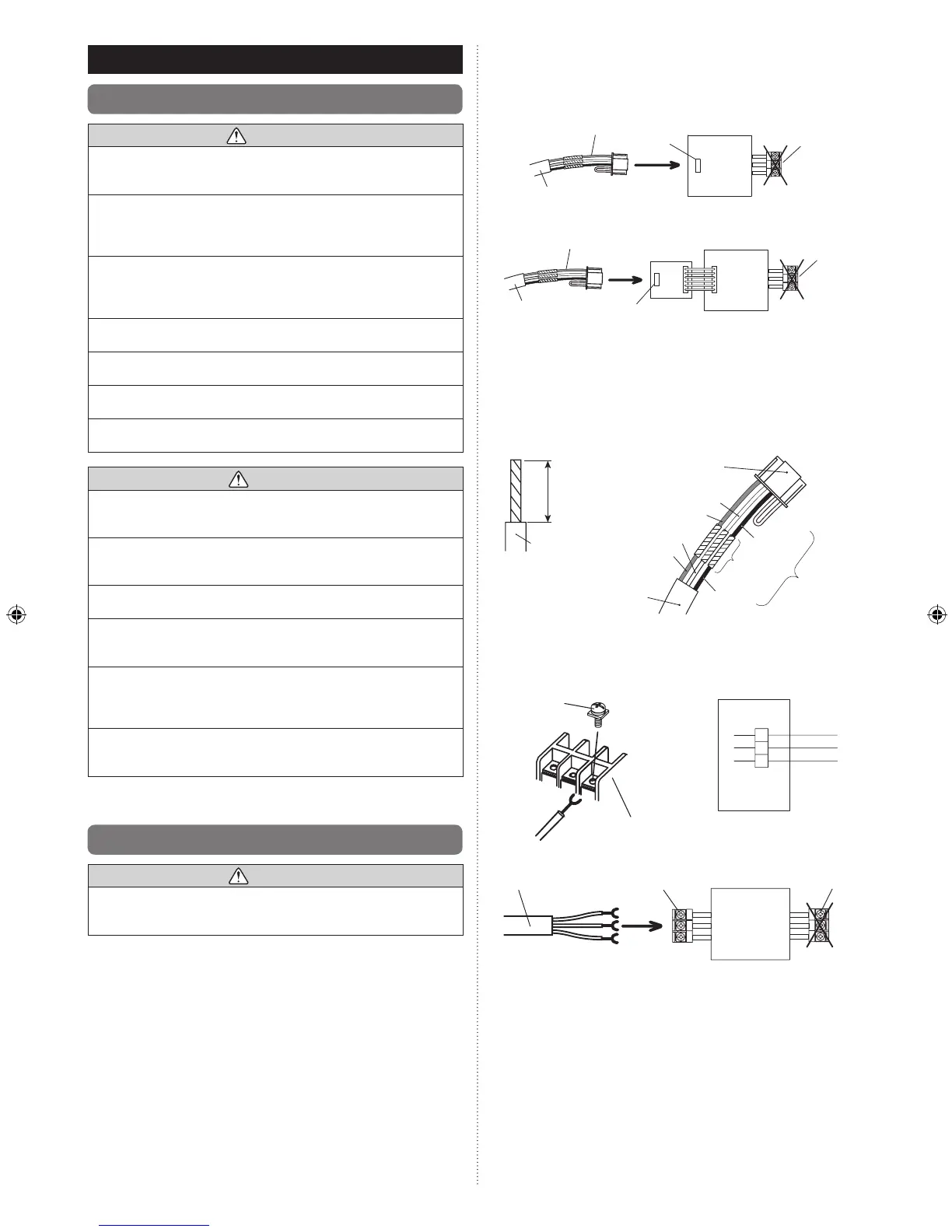
5.2.1 When connecting to the wall mounted type
and the oor type connector
Connect the remote controller cable to the connecting cable and insert it to
the connector.
Pattern 1
Connecting cable
Connecting cable
Remote controller
cable
Remote controller
cable
Connector
Connector
Communication
kit (option)
Indoor unit
Indoor unit
PCB
PCB
Outdoor
unit /
power
supply
terminal
block
Outdoor
unit /
power
supply
terminal
block
Pattern 2
Modify the cable as per below methods.
Use a tool to cut off the terminal on the end of the remote controller cable (1)
and then remove the insulation from the cut end of the cable as shown
in Fig. 1.
Connect the remote controller cable and connecting cable as shown in (2)
Fig. 2.
Be sure to insulate the connection between the cables.(3)
Fig. 1
Wire
Connecting
cable
Connector
White
White
Red
Red
Black
Black
Insulated
connection
Remote
controller cable
25/32 in.
(20 mm)
Fig. 2
5.2.2 When connecting to the exclusive terminal
block
Connect the end of remote controller cable directly to the exclusive terminal
block.
M4 screw
Terminal block
Black
3
2
1
White
Red
Indoor unit
side
Remote controller
cable
Remote controller
terminal block
Outdoor unit /
power supply
terminal block
Indoor unit
PCB
It may be failed if it is connected to the outdoor unit or the terminal block for
power supply.