GFSE-Std-0499
2 2
13
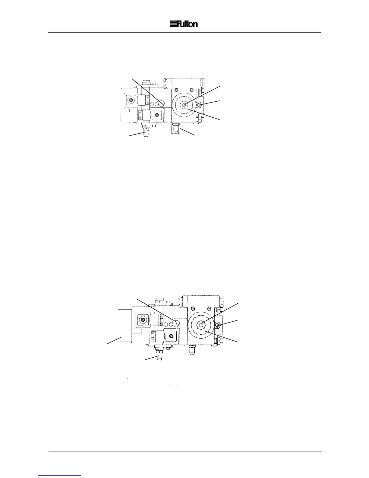
ADJUSTMENTS ACTION
A Main and Pilot Gas Governor. Turn clockwise to increase gas pressure. Range 4 - 20 mbar.
B First and second stage -
initial lift adjuster, main gas valve.
C Main gas throughput Slacken locking screw, turn fluted knob anticlockwise
to increase, clockwise to decrease.
D Gas supply test point
E Boiler side test point
F Low gas pressure switch
B
E
F
C
D
ADJUSTMENTS ACTION
A Main and Pilot Gas Governor. Turn clockwise to increase gas pressure. Range 4 - 20 mbar.
B Pilot gas range. Turn anticlockwise to increase and clockwise to decrease rate.
C First and second stage -
initial lift adjuster, main gas valve.
D Main gas throughput Slacken locking screw, turn fluted knob anticlockwise to
increase, clockwise to decrease.
E Gas supply test point
F Boiler side test point
C
D
B
E
F
MONOBLOC GAS VALVES (FIG. 9)
ADJUSTMENTS 6E - 30E (MBDLE 407/412 B07)
(With in built pilot bypass valve)
Pilot gas rate should be set to a maximum of 10% of the full fire gas throughput.
A
A
ADJUSTMENTS 6E - 30E (MBDLE 407/412 BO1)
The Monoblock gas valve operates in two stages through two main shut-off valves:-
Stage 1. The first valve opens fully and the second valve opens slowly such that the
maximum gas flow rate during the start gas proving period does not exceed 30% of the full
firing rate.
Stage 2. The second valve is fully open.
NOTE: The time taken to open fully is set by the adjustment of the first and second stage initial lift adjuster.