GFSE-Std-0499
2 2
16
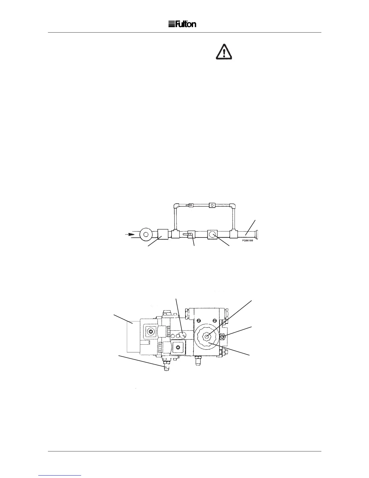
GOVERNOR
GAS START
VALVE
GAS STOP
VALVE
MAIN GAS
PILOT
ORIFICE
TUBE
PILOT
GAS
BALL VALVE
FIG. 10 L.P. GAS TRAIN
MONOBLOC ADJUSTMENTS LPG Boilers (MBZRDLE 405/412 BO1)
A
B
E
C
F
D
ADJUSTMENTS ACTION
A Main Gas Governor. Turn clockwise to increase gas pressure. Range 4 - 50 mbar.
B First and second stage -
initial lift adjuster, main gas valve.
C Main gas throughput Slacken locking screw, turn fluted knob anticlockwise
to increase, clockwise to decrease.
D Gas supply test point
E Boiler side test point
F High gas pressure switch
L.P. GAS
WARNING
Do not change the boiler fuel without
consulting the boiler manufacturer.
2.18 GAS SUPPLY - PROPANE / BUTANE
Note: LPG Boilers should be installed to the requirements of IGE/UP/10 March 2001
An L.P. gas boiler is similar in design to a natural gas boiler, the main differences are important and
must be taken into account when installing the boiler and ordering spare parts.
When installing an L.P. gas boiler, the feed from the bulk tank supply must be fitted with a supply
governor which is set to reduce the supply feed pressure to the boiler governor to 30 in. (80 mbar)
Water Column or less.
For PROPANE:-The boiler governor must be adjusted to give a firing pressure of 10 in. (25 mb) water
column at the test point provided at the elbow on the gas train.
For BUTANE:-The boiler governor must be adjusted to give a firing pressure of 8 in. (20 mb) water
column at the test point provided at the elbow on the gas train.
Gas Pressure Alarm Indicator Light
For L.P.G. applications the inlet pressure switch is used to protect the system from over pressure
and should be set at 100 mbar.