J OIL-E-08 2008
12
2.16 COMMISSIONING THE BOILER - continued
INSPECTION
(a) Ensure the boiler has been washed out after installation.
Conduct a water analysis before operating the boiler.
Examine the probes in the water column and the boiler shell.
Replace any damaged probes.
(b) Remove the burner and check the electrodes have not been damaged and that their settings
arecorrect.Iftheburneristtedwithaphotocell,removeitandcheckfordamage.
(c) Replace the burner and reconnect the cooper oil line(s) to the oil nozzle assembly, ensuring
these connections are tight. Reconnect the ignition leads and replace the sensor.
(d) Ensure all wiring connections are correct and all terminal screws are tight.
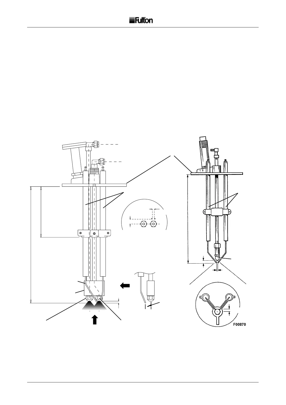
FIG. 10 NOZZLE AND IGNITION ASSEMBLIES
Burner Plate
Electrodes
Electrodes
Electrode Tips
Bent to align with
Low Flame (Start)
oil supply nozzle
80
O
Spray
80
O
Spray
Fuel Nozzle
5mm
300mm
300mm
5mm
5mm
DOUBLE NOZZLE
TWO-STAGE LIGHT
40E - 60E
SINGLE NOZZLE
SINGLE-STAGE LIGHT
10E - 30E
130mm
High Fire Oil Supply
Low Fire (Start)
Oil Supply
Low Fire Oil Supply
12mm
High Fire Oil Supply
View on
arrow 'A'
5mm
12mm
Electrode settings
relative to nozzles
View on arrow 'B'
Arrow 'B'
12mm
Note: Always place the highest value nozzle
(engraved on the side of the nozzle) into the low
reoilsupplyportinthemanifold.
Nozzle Manifold
Arrow 'A'
2
2