Fig. 08:
Type-
dependent
pin allocation
Fig. 10:
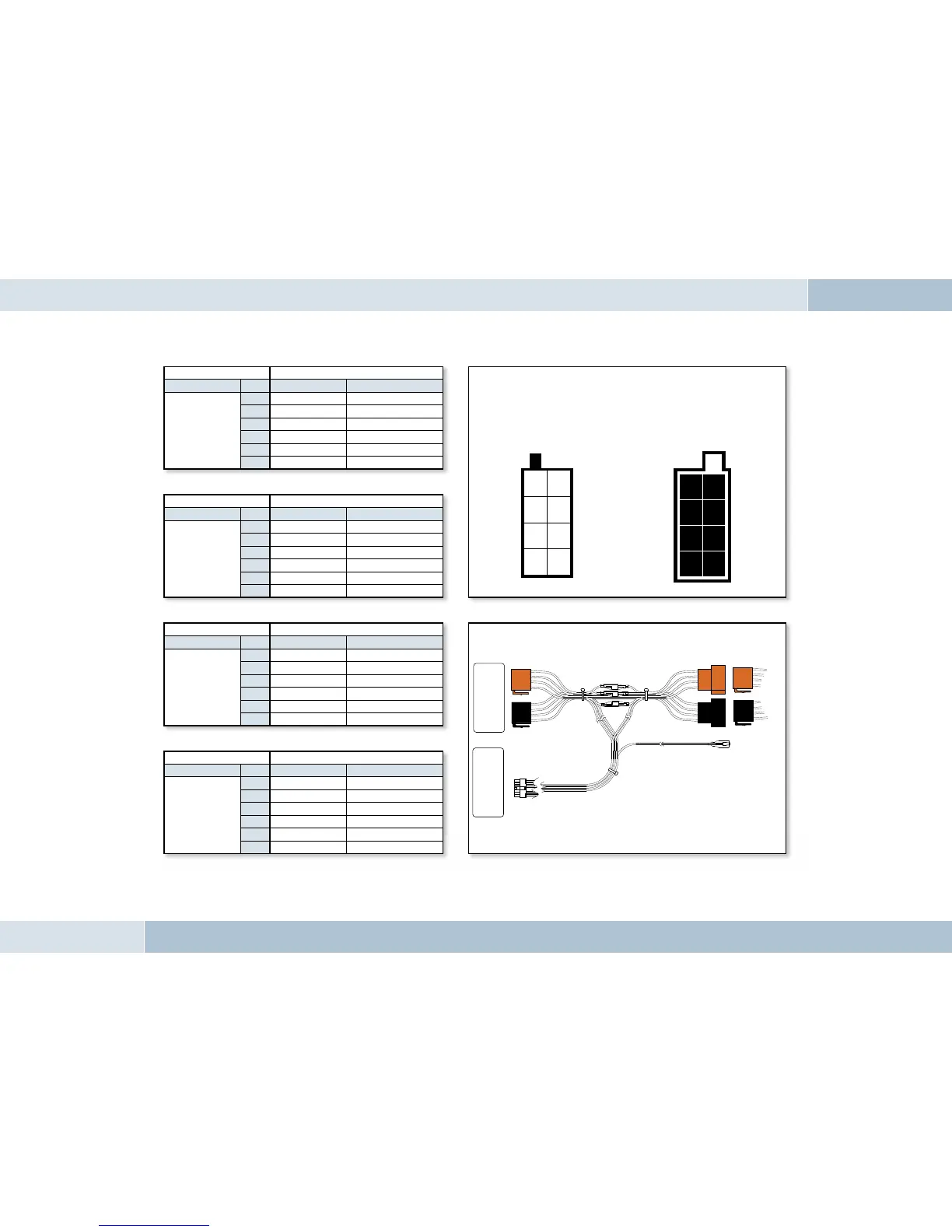
Connection system
Socket contact housing
Wiring of power supply connectors
Radio model Pin Wire colour Function
Audi,
Volkswagen,
Grundig
1
2
Mute
3
4
blue Ignition (15)
7
red Permanent positive (30)
8
brown Ground (31)
Socket contact housing
Radio model Pin Wire colour Function
Ford,
Mercedes,
Porsche,
Becker
1
2
3
Mute
4
red Permanent positive (30)
7
blue Ignition (15)
8
brown Ground (31)
Socket contact housing
Radio model Pin Wire colour Function
Blaupunkt
1
2
Mute
3
4
red Permanent positive (30)
7
blue Ignition (15)
8
brown Ground (31)
Socket contact housing
Radio model Pin Wire colour Function
Philips
1
Mute
2
3
4
red Permanent positive (30)
7
blue Ignition (15)
8
brown Ground (31)
EGO FLASH
Socket wiring from
the rear (see table)
Plug wiring from
the rear
21
43
65
87
12
34
56
78
Autoradio
Elektronikbox
KFZ-Kabelbaum
Fig. 09:
Plug wiring scheme
Car audio
Electronics box
Vehicle wiring harness