EGO FLASH
List of illustrations
Fig. 01 Scope of delivery 9
Fig. 02 Signal orientation of Bluetooth
®
antenna 11
Fig. 03 Installation location for electronics box 12
Fig. 04 Installation location for microphone 12
Fig. 05 Installation dimensions of electronics box 13
Fig. 06 Connecting the Mini-ISO-connector 16
Fig. 07 Installation procedure 17
Fig. 08 Type-dependent pin allocation 18
Fig. 09
Plug wiring scheme 18
Fig. 10 Connection system 18
Fig. 11 a/b Changing power supply wiring 19
Fig. 12 Connecting external loudspeakers 20
Fig. 13 Connecting the electronics box 21
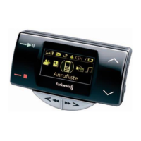
Fig. 14 Status bar 24
2