6.6 Connecting the components to the electronics box
The individual components are connected to the electronics box as follows:
[1] Plug the microphone jack into the jack socket with the microphone symbol
[2] The electronics box line-out must be connected to the car audio line-in. Depending on the car audio line-in
confi guration, one of the following cables is required:
→ Connection cable 0.14 in stereo jack to 0.14 in stereo jack (l = 4.92 ft)
→ Connection cable 0.14 in stereo jack to RCA plug (l = 4.92 ft)
→ Connection cable 0.14 in stereo jack to Mini-ISO (l = 4.92 ft)
[3] The control console must be connected to the control console input.
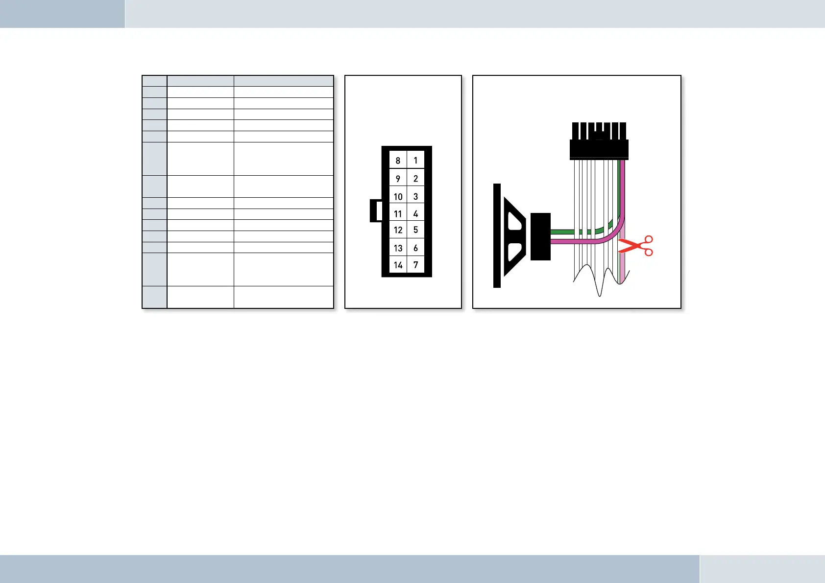
Pin Colour Function
View of the plug side,
from which the wiring is
fed in the plug housing
(with pin allocation)
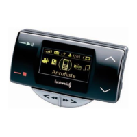
Connection option for additional speakers on pin 7
(purple lead) and pin 14 (green lead) of the 14-pin plug
1 Brown Ground (31)
2 Yellow Radio mute
3
4
5
6 White
Car audio speaker
output +
(front right)
7 Purple
Speaker lead +
(front right)
8 Red Permanent positive (30)
9 Blue Ignition (15)
10
11
12
13 Black
Car audio speaker
output -
(front right)
14 Green
Speaker lead -
(front right)
18
|
19
Fig. 12:
Additional external
loudspeakers