9
2. WIRING
2.1 Processor Unit Wiring
For detailed information about NMEA 2000 wiring, see “Furuno CAN bus Network Design Guide”
(TIE-00170) on Tech-Net.
Note: Connect/disconnect cables after turning the power off.
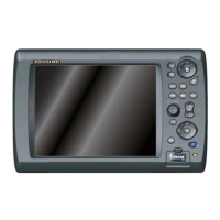
Control Unit
MCU-001 and/or DCU12
12-24 VDC
NMEA 0183
equipments
(ex. GP-320B)
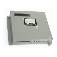
Radar Sensor or
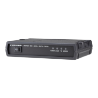
PSU-013
USB port*
(Mouse, keyboard)
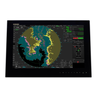
Display Control Unit DCU12
or External display
(MU-155C/170C, etc.)
Video interface
devices
External speaker*
NMEA 2000 equipment
(SC-30, FI-50, GP-330B,
etc.)
*: For USB, speaker and microphone connections,
appropriate cables should be fastened to the metal
plate beneath of connectors by the cable tie.
Metal plate
DPYC-6 cable
(within 5 m)
2.5C2V or 3C2V
coaxial cable
DVI-D/D SINGLELINK
5 m: supplied with DCU12
10 m: option
MOD-Z072 cable
5 m: supplied with
MCU
2 m, 10: option
7 pin: MJ-A7SPF0007
(5 m, option)
18 pin: FRUDD-18AFFM
(2 m, supplied)
Ship's ground
Ground cable
IV-8sq.
CB-05BFFM, 1 m/2 m
MOD-ASW
0001 cable
(10, 15, 20,
30 m)
Network sounder,
IP camera, etc.
MOD-WPAS cable (3 m)
(supplied with DCU)
MOD-Z072 cable
(2, 5, 10, 10 m)
 Loading...