4
2. WIRING
2.1 Wiring
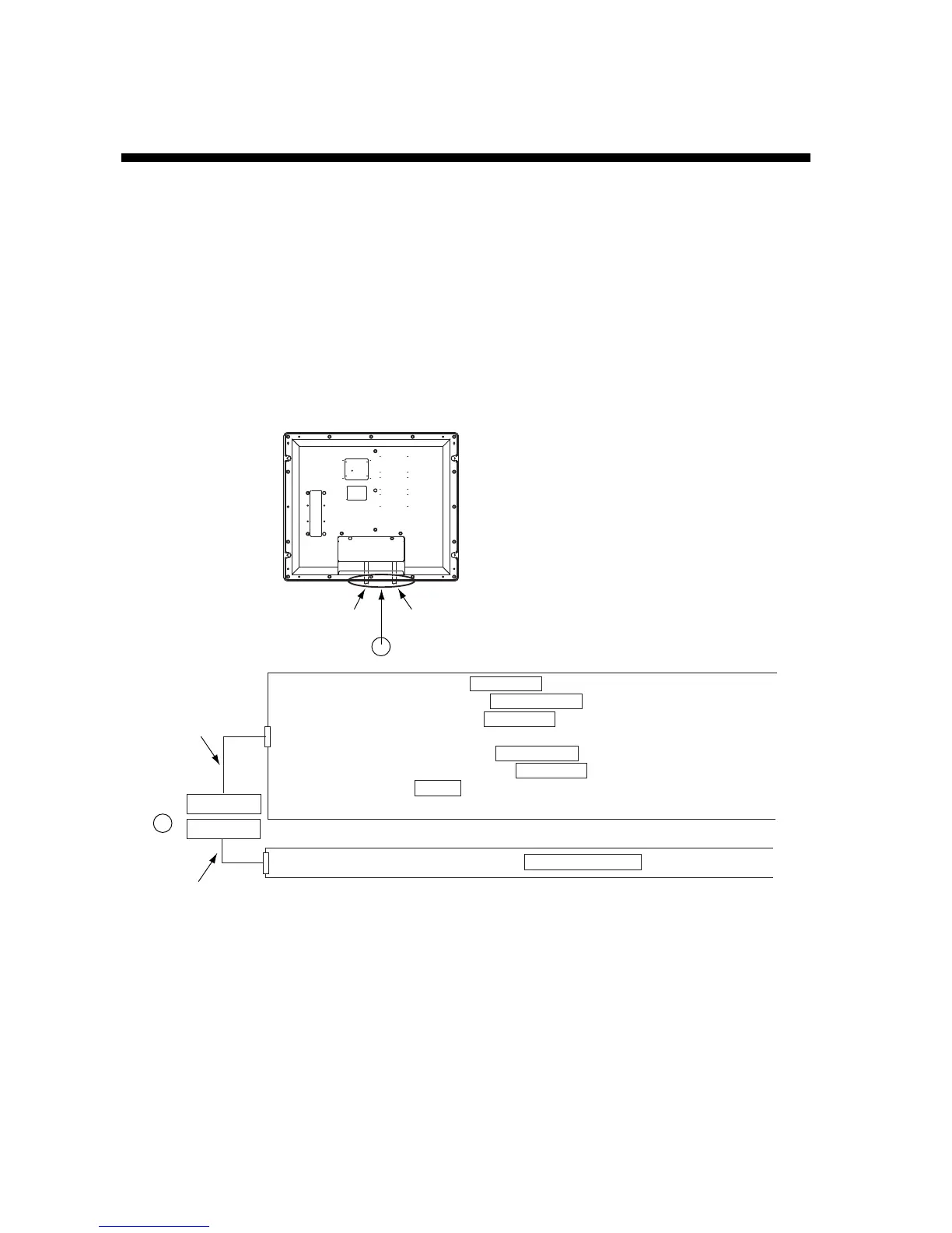
Connect equipment to the MU-201C by referring to the drawings in this section and the
interconnection diagram of this manual. A cable with a connector at both ends is provided to
connect equipment.
General-purpose monitor
To use the MU-201C as a general-purpose monitor, connect equipment with the optional
cable assembly, 3COX-2P-6C (5 or 10 m) or DVI-D/D SINGLELINK.
A
A
RGB port
DVI port
FCV-30: PROCESSOR UNIT RGB OUT port
FSV-24/30: PROCESSOR UNIT CN-A104/109 port
FCV-1200L: INTERFACE UNIT RGB OUT port
FR-2105: Connector on RGB BUFFER board in the display unit
GD-280/380/680: DISPLAY UNIT EXT VIDEO port
CH-250/270/300: INTERFACE UNIT RGB OUT port
CI-68/88: Connect to CN-A1 port in the control unit with the conversion cable
(66S1242, 0.3 m)
FAR-2117/2817: PROCESSOR UNIT DVI-D MONITOR port
3COX-2P-6C
(5/10 m)
DVI-D/D SINGLELINK 5M
Cable entrance
for power cable
Cable entrance for signal cable
(The connector with no EMI core should
be connected to the DVI port.)
Note 1: Even when the power switch is off, electric current flows slightly. Connect the power
line via a double-contact breaker.
Note 2: The MU-201C does not have a hot plug function. When the power switches of the
MU-201C and the equipment connected are on, do not connect or disconnect
equipment to prevent damage to equipment.
 Loading...