Home
Furuno
Autopilot System
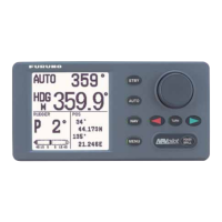
NAVpilot-511
Installation Manual
Page 16 (Button Type Remote Controller FAP-6211;6222)
Furuno NAVpilot-511 - Button Type Remote Controller FAP-6211;6222; Lever Type Remote Controller FAP-6221;6222
67 pages
Manual
To Next Page
To Next Page
To Previous Page
To Previous Page
Loading...
1. INS
T
ALLA
TION
OF UNITS
1-8
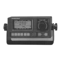
Button t
y
p
e remote contro
ller F
AP-621
1/6222
F
AP-621
1, bulkhead
mounting
Lever type remote co
ntroll
er F
AP-6221/6222
Allow sufficient space around the unit f
or maintenance.
F
AP-6221, bulkhea
d mounting
15
17
Table of Contents
Main Page
Default Chapter
3
Safety Instructions
3
Table of Contents
4
System Configuration
5
Equipment Lists
6
Standard Supply for Navpilot-500
6
Standard Supply for Navpilot-511
6
Optional Supply
7
1 Installation of Units
9
Control Unit FAP-5001/5011
9
Flush Mounting
10
Desktop Mounting (FAP-5001 Only)
11
Control Unit, Desktop Mounting
11
Processor Unit FAP-5002
12
Rudder Reference Unit FAP-6111
13
Mounting the Rudder Reference Unit
13
Remote Controllers (Option)
14
Dial Type Remote Controller FAP-5551/5552
14
FAP-5551, Bulkhead Mounting
14
Mounting the Hunger for FAP-5551/5552
15
Reversing the Switch and Dial Blocks
15
Button Type Remote Controller FAP-6211/6222
16
Lever Type Remote Controller FAP-6221/6222
16
Contents of OP64-4
17
Contents of OP64-5
17
FAP-6221, Flush Mounting (OP64-4)
17
Distributor FAP-6800
18
FAP-6221, Flush Mounting (OP64-5)
18
FAP-6800, Desktop Mounting
18
Wiring System
19
Processor Unit
20
How to Fix Cables to the Clamp
20
Processor Unit, Clamp Stopper
20
How to Insert the Cable into the Cable Blocks
21
Picking up the Cable Block
21
Cable Block, Upper
21
Power and Motor Cable
22
Processor Unit, Inside View
22
Connecting Motors
23
Connecing a Reversible Pump
23
Connecing a Hydraulic Linear Drive
23
Connecing a Solenoid Valve
23
Connection of Terflex Linear Sensor
24
Control Unit
25
Connection of Six Control Units
25
Example Remote Controller Connections
26
Connection of Dial Type
26
No Distributor
26
Dial Type Remote Controller
26
Connection of Six Dodge Remote Controllers
27
Button or Lever Remote Controller with Distributor
27
Dodge Remote Controller with Distributor
27
Processor Unit
27
Prohibited Remote Controller Connections
28
Wrong Connection 1
28
Wrong Connection 2
28
Connection of Instruments FI-30
29
Connection Using the NMEA IN/OUT Ports on FAP-5002
29
Connection Using the NMEA in and NMEA out Ports on FAP-5002
29
Wrong Connection 3
29
Input/Output Sentences
30
3 Adjustments
31
How to Access the Installation Menu
31
Dockside Setup Menu
32
Selecting Your Drive Unit
32
Drive Unit Options Window
32
Selecting the Type of Rudder Reference Unit
33
Bleeding Air in the Oil Cylinder
33
Rudder Indicators (Ex. Navpilot-500)
33
Selecting Boat Type
34
Entering Boat Length
34
When Selecting “Use Arrow Keys”
34
When Selecting “Using RRU”
34
Entering Maximum Speed
35
Adjusting Rudder Reference Unit
35
Adjust RRU Menu (Ex. Navpilot-500)
35
Setting Rudder Auto Movement Limit
36
Setting Manual Rudder Movement Limit
36
Checking Rudder Status
36
Rudder Test Options Window
36
Setting Course Changing Speed
37
Selecting Compass Type
37
Rudder Setup and Auto Test Menu
37
Compass Type Options Window
37
Setting Compass Baud Rate
38
Setting the Rudder at the Zero Position
38
Compass Baud Rate Options Window
38
Sea Trial Menu
39
Calibrating the Heading Sensor (for PG-500, PG-1000)
40
Compass Calibration Options Window
40
Using Magnetic Variation
41
Offsetting the Heading Data
41
Magnetic Variation Options Window
41
Automatic Distortion Compensation (for PG-500)
42
Auto Calibration Options Window
42
Set Rudder Zero Options Window
42
Memorizing Your Boat’s Characteristics
43
Auto Tuning Options Window
43
Display Setup Menu
44
Speed Unit Options Window
44
Data Calibration Menu
46
STW (Calibration)
46
Depth (Calibration)
46
Other Settings
47
Setting the Remote Controller
47
System Setup Menu
47
Remote Controller 1, 2 Options Window
47
Selecting Course after the Remote Mode Is off
48
Course after Remote Options Window (Ex. Navpilot-500)
48
Course after Remote Controller Is Turned off
48
NMEA Port Setup
49
Setting the Name for Port
49
Setting the NMEA Format
49
Setting the Sentences
50
Sentence Selecting Window
50
Sentence Options Window
50
Using Settings Selected on Other Control Unit
51
Confirming the Input Sentences
51
Receiving Sentence Window
51
Clearing All Data
52
System Setup Menu (through the Main Menu)
52
Running Simulation Program
53
Simulation Mode Options Window
53
Simulation Mark (Ex. STBY Mode)
53
Indicates the Number of Typical Material
55
Furuno Electric CO., LTD.
57
Other manuals for Furuno NAVpilot-511
Quick Guide
8 pages
Related product manuals
Furuno NAVpilot-500
73 pages
Furuno NAVpilot-700
102 pages
Furuno NAVpilot-300
101 pages
Furuno NAVpilot-711C
176 pages
Furuno FAP-330
124 pages
Furuno FAP-55
101 pages