8
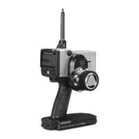
Do not cover/hold the built-in antenna part of T3PV-2.4G
transmitter by your hand during running.
Do not put any conductive plate/sticker on the antenna part.
Otherwise, the operating range may become shorter.
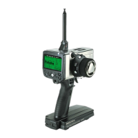
Antenna (Built-in)
Power switch turned on: Beep confirm-
ation sound is generated and the model
name is displayed for about two seconds
and then the initial screen appears.
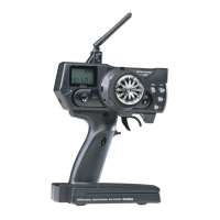
Steering Trim Lever (DT1)
Steering Wheel
Throttle Trigger
Grip Handle
Battery cover
Throttle Trim Lever (DT2)
Press for about 1 second→ON
Press for about 1 second→OFF
Adjusts the steering in small increments
so the model will run straight.
Tu rn model to left or right.
Channel 3 Switch
Tu rn channel 3 servo to left
or right.
Select Key
Press the Select key
to select the desired
function screen.
LED
ON→ Solid
Low battery→ Blinks
It is used to change a setup.
Press the +key and −key sim-
ultaneously for about 1 second
→ Value is reset.
Steering D/R Lever (D/R)
Adjusts the throttle in small increments so
the model will not move at neutral.
Adjust the vehicle's steering
sensitivity across the entire range.
Digital trim DT1, DT2, and D/R operation
Push the lever to the left or right (up or down).
The current position is displayed on the LCD screen for about
two seconds. Each step is indicated by a tone. When the trim
exceeds the maximum trim adjustment range, the beep tone
will change and the servo will not move any further.
Remember, the trims are digital so the position of each trim is
remembered for each model separately.
Control the speed of the model and
movement forward and backward.
(Initial screen)
• Model memory number display
• Battery voltage display
(*1)
(*1)
(*1)
(*1)
The antenna is inside of this part.
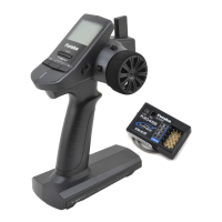
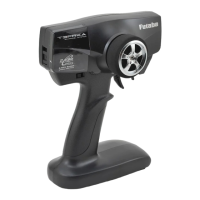
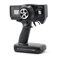
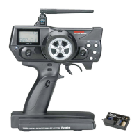
Nomenclature/Handling
Transmitter T3PV-2.4G
As with all radio frequency
transmissions, the strongest
area of signal transmission
is from the sides of the
antenna(built-in). As such,
the antenna (arrow direction)
should not be pointed directly at
the model.