Antenna #OAXIALCABLE
Tactile switch / LED
29
Before Using
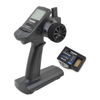
Receiver Terminology
How to link the transmitter and the receiver
Each transmitter has an individually assigned, unique ID code. In order to start opera-
tion, the receiver must be linked with the ID code of the transmitter to which it is being
paired. Once the link is made, the ID code is stored in the receiver and no further link-
ing is necessary unless the receiver needs to be used with another transmitter.
Link procedure
1
Bring the transmitter and the receiver close to each
OTHERWITHININCHESHALFMETER
2
Turn on the transmitter.
3
Turn on the receiver.
4
Push the tactile switch of the receiver.
When the link is complete, the LED in the receiver
changes to solid green.
Connectors
B/4 :CH4 servo(CH4)/Power connector
3 :CH3 servo(CH3)
2 :Throttle servo(CH2)
1 :Steering servo(CH1)
DSC :DSC connector
No signal reception
Red : On
Receiving signals
Green: On
Receiving signals, but ID is unmatched. Green: Blink
Unrecoverable failure (EEPROM, etc.) Red and Green turn on alternately
LED status vs receiver's condition:
Precaution:
)F THERE ARE MANY &!334 SYSTEMS TURNED ON IN CLOSE PROXIMITY TO THE 2&32&&2&3 YOUR
receiver might not link to your transmitter. In this case, even if the receiver's LED stays solid green, un-
fortunately the receiver might have established a link to one of other transmitters. This is very dangerous
if you do not notice this situation. In order to avoid the problem, we strongly recommend you to double-
check whether your receiver is really under control by your transmitter by giving the stick input and then
checking the servo response.
n
Warning
j
After the linking is done, please cycle receiver power and check if the receiver to be linked is really
under the control of your transmitter.
l
Do not perform the linking procedure with motor's main wire connected or the engine operating as
ITMAYRESULTINSERIOUSINJURY
*Please refer the table below for LED status vs receiver's condition.
 Loading...