V
FUTABA 9Z
THE UNOFFICIAL WORKSHOP MANUAL
WARNING: THE INFORMATION IN THIS MANUAL IS FOR INFORMATION PURPOSES ONLY AND MAY BE INCORRECT, CAUSE DAMAGE
TO YOUR RADIO OR INJURY TO YOURSELF AND OTHERS. IF YOU USE THIS MANUAL YOU DO SO SOLEY AT YOUR OWN RISK.
www.jamesandtracy.co.uk
Copyright 2012 jamesandtracy.co.uk
Page 28 of 84
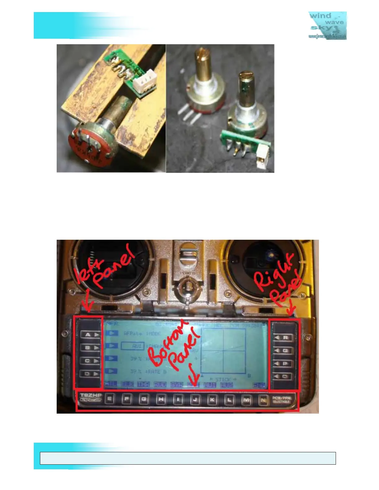
Figure 20 Desolder the connector PCB (green) from the POT
3.5. Replacement of LCD button panels
The 9Z transmitter, like its predecessor the 9V, uses software buttons that are activated
by clicking the corresponding button on the LCD button panel. However, unlike the 9V,
these button panels are manufactured as self adhesive units (see Figure 21) and it is
common for these panels to become worn and fail over the life of the transmitter.
Figure 21 The three LCD Button Panels shown on a 9ZHP WC2
The primary issue with replacing these panels is finding a supplier that still has stock of
the required spare parts. At present it appears that stock of the original 9ZAP/ZHP and