Wiring the Optoisolated Digital Inputs
To take full advantage of optoisolation, an isolated power supply should be used to provide the voltage at the input
common connection. Connecting the ground of the isolated power to the ground of the controller will bypass
optoisolation and is not recommended if true optoisolation is desired.
If there is not an isolated supply available, the 5 V
DC
, 12 V
DC
, and GND controller references may be used to power
INCOM/LSCOM. The current supplied by the controller references are limited, see +5, ±12V Output Specifications
for more information. Using the controller reference power completely bypasses optoisolation and is not
recommended for most applications.
Banks of inputs can be configured as sinking or sourcing, depending on how INCOM/LSCOM are wired. Connecting
the isolated ground to INCOM/LSCOM will configure the inputs as sinking. Connecting the isolated supply +V to
INCOM/LSCOM will configure the inputs for sourcing.
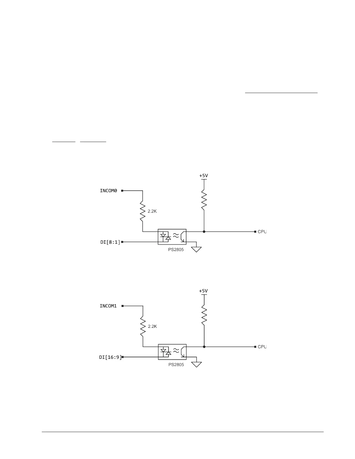
Figure 3.6 - Figure 3.10 are the optoisolated wiring diagrams for powering INCOM/LSCOM (Bank 0) and
INCOM/LSCOM (Bank 1) and their corresponding inputs.
Chapter 3 Installation ▫ 12 DMC-40x0 UL Installation Manual
Figure 3.6: Digital Inputs 1-8 (DI[8:1])
Figure 3.7: Digital Inputs 9-16 (DI[16:9])

 Loading...
