Do you have a question about the Gamatronic POWER+ PREMIUM 60 and is the answer not in the manual?
Essential precautions and best practices for installation and operation.
Prohibited actions to prevent damage or injury during operation and handling.
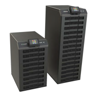
Physical dimensions of the UPS unit and its components.
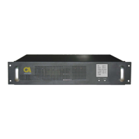
Requirements for fitting the UPS into a standard 19-inch rack.
Instructions on how to remove the UPS's wheels for installation.
A guide to verify each step of the installation and configuration process.
A template for sketching system wiring and connections.
Step-by-step instructions for installing the UPS system.
Details on special-purpose terminal connections for UPS.
Steps for powering on and preparing the UPS for operation.
Guided setup process for configuring the UPS parameters.
Procedures to verify the UPS functionality.
Steps to gain access to the UPS modules by removing side panels.
Procedure for physically installing a UPS module into its slot.
Procedure for physically detaching and removing a UPS module.
Specific instructions for inserting modules during initial system setup.
Detailed steps for replacing an existing module with a new one.
Procedure for adding a new module to an operational UPS system.
Procedure for safely removing a module from an operational UPS system.
Steps to engage the maintenance bypass for servicing.
Steps to exit bypass mode and restore normal UPS function.
Description of the Gamatronic G4 network interface device.
Description of the Gamatronic G-Eye environmental monitoring system.
Detailed technical data for the UPS system.
Specific technical data for the UPS controller unit.
| Apparent Power | 60 kVA |
|---|---|
| Topology | Online Double Conversion |
| Frequency | 50/60 Hz |
| Input Voltage | 380/400/415 V |
| Output Voltage | 380/400/415 V |
| Battery Type | Sealed, maintenance-free lead-acid |
| Communication Interface | RS232, USB, SNMP |
| Operating Temperature | 0 to 40 °C |
| Efficiency | Up to 94% (AC-AC) |
 Loading...