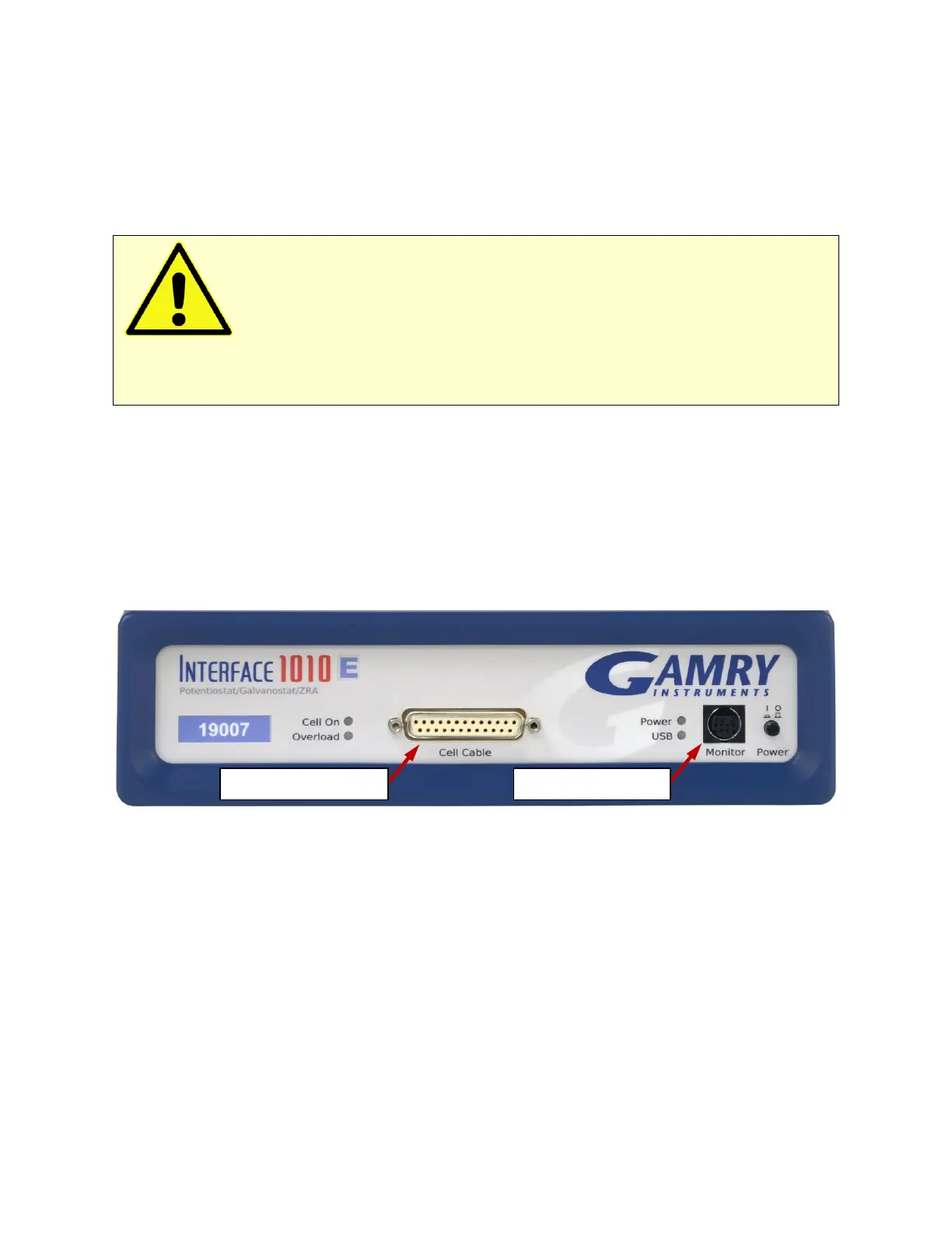
Panel Indicators and Connectors – Front Panel
42
• One part of the Power PC’s power-up self-test has failed.
An Interface 1010’s Power LED blinks when that instrument is selected in the Framework’s Instrument
Manager. This allows easy identification of a specific instrument in a Multichannel system without looking at
the instrument Serial Label on the bottom of the instrument chassis.
Finally, the Power LED continuously blinks if the instrument is subject to an over-temperature condition. In this
case, the instrument is not usable until it has been powered down, allowed to cool, and restarted.
Cell Cable Connector
The Cell cable connector is a 25-pin D type connector used to connect the Interface 1010 to an
electrochemical test cell. It is normally used with a Gamry Instruments supplied cell cable.
In addition to the pins used for cell connections, the Interface 1010 Cell Connector also uses four pins to read a
cell cable ID. Gamry software can compensate for the cell cable characteristics for optimal system performance,
especially in EIS (Electrochemical Impedance Spectroscopy).
The cell connections are discussed at great length in Chapter 5. A pin-out of the Cell Cable connector can be
found in Appendix B.
Monitor Connector
The Monitor Connector is an 9-pin DIN-type connector. It contains two analog output signals; one analog
input signal is used for connection of the Interface 1010 to external devices, a temperature input, and an
analog input for measurement of analog input signals. It is not needed for any standard Gamry Framework
electrochemical tests.
Additional information on this connector, its uses, and its signals is in Appendix C.
The USB LED
The USB LED is located just below the Power LED. It is a tri-color LED, able to glow green, orange, or red.
The USB LED is unlit when:
• The Interface 1010 is not powered.
• The Interface 1010 does not have a USB cable plugged into its rear-panel USB port.
Caution: The Power LED indicates power status, power-up tests have passed, to identify
instruments, and to indicate latch-up caused by an over-temperature event. Never rely on the PWR LED as
a true power-status indicator. Always unplug the Power In connection if you suspect your Interface 1010 is
malfunctioning.