Interface 1010 Cell Connector
74
Appendix B: Interface 1010 Cell Connector
Chapter 5 describes the connections between a cell cable and an electrochemical cell. This appendix describes
the other end of the cell cable.
Multiple pins assigned to the same signal are connected together on the Interface 1010’s Potentiostat board. If
you need to connect this signal outside the Interface 1010, you need a wire connected to any one of the D-
connector pins.
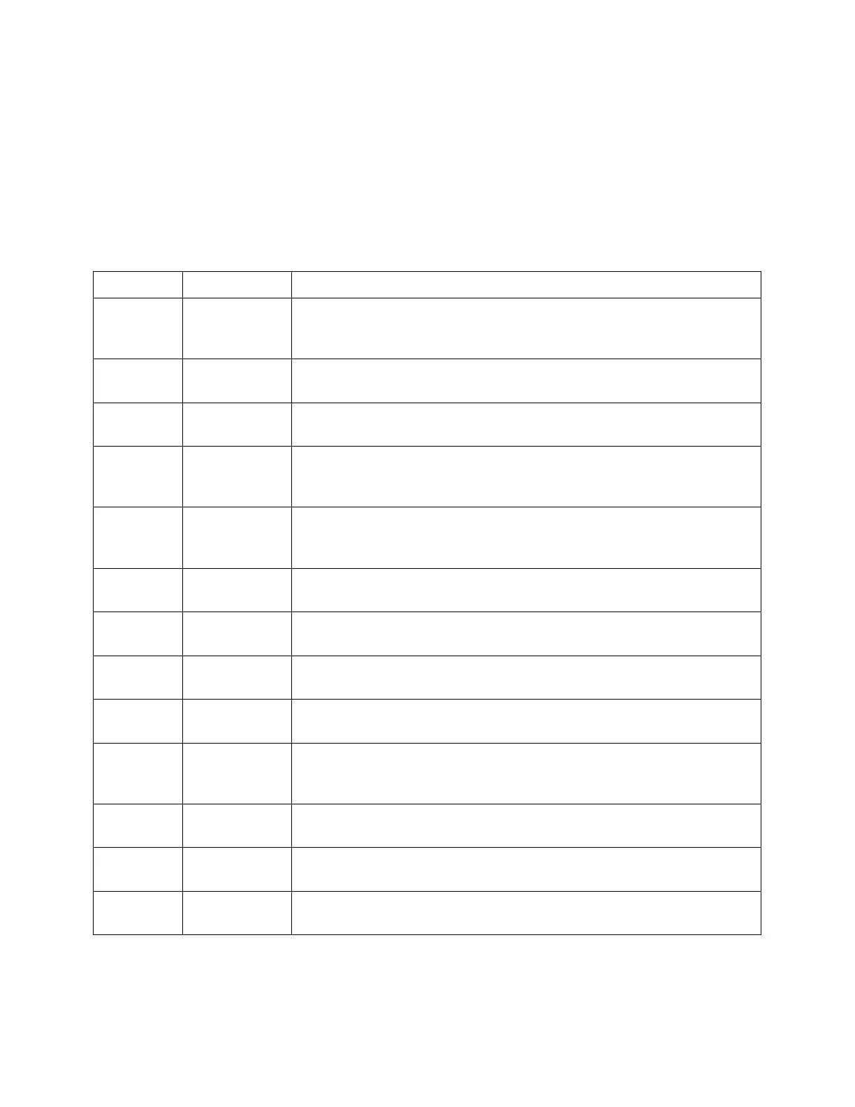
Table B-1
Cell Connector
Connected to the working electrode in most cases (see Chapter 5). This lead
has a 261 Ω resistor in the cell end of the cable. Custom cell cables are likely
to require a similar resistor.
The shield for the working-sense input. Driven to the same potential as Pin 1.
Left open at the cell end of the cell cable.
The shield for the reference electrode input. Driven to the same potential as
Pin 16. Left open at the cell end of the cell cable.
5, 7, 10, 11,
18, 19, 22,
24
The potentiostat’s floating ground. Can be used to shield the cell if very low
currents need to be measured. Also used as a shield for the counter electrode
cable.
With an Interface 1010, used to sense the potential of the counter electrode.
Allows accurate ZRA mode even with significant cell current through counter
lead’s resistance.
One of four cable-ID bits. Used to identify the type of cell cable attached to
the unit. Pull to a logic High through a resistor. Ground to set the bit low.
One of four cable-ID bits. Used to identify the type of cell cable attached to
the unit. Pull to a logic High through a resistor. Ground to set the bit low.
The shield for the working electrode input. Connected to Floating Ground.
Left open at the cell end of the cell cable.
Connected to the working electrode. The cell current flows through this pin.
Connected to the reference electrode in most cases (see Chapter 5). This
lead has a 261 Ω resistor in the cell end of the cable. Custom cell cables are
likely to require a similar resistor.
One of four cable-ID bits. Used to identify the type of cell cable attached to
the unit. Pull to a logic High through a resistor. Ground to set the bit low.
One of four cable-ID bits. Used to identify the type of cell cable attached to
the unit. Pull to a logic High through a resistor. Ground to set the bit low.
Connected to the cell’s counter electrode. The cell current flows through this
connection.