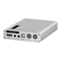
Console module »DVI-CON-2-Fiber«
Computer and console modules · 157
Connection to the matrix switches
Trans. 1|Tx: Insert the LC plug of a compatible optical fibre cable. Connect the other
end of the cable to the
Rx interface of a Dynamic Port provided at the first matrix
switch.
Trans. 1|Rx: Insert the LC plug of a compatible optical fibre cable. Connect the other
end of the cable to the
Tx interface of the same Dynamic Port provided at the first
matrix switch.
Trans. 2|Tx: Insert the LC plug of a compatible optical fibre cable. Connect the other
end of the cable to the
Rx interface of a Dynamic Port provided at the second matrix
switch.
Trans. 2|Rx : Insert the LC plug of a compatible optical fibre cable. Connect the other
end of the cable to the
Tx interface of the same Dynamic Port provided at the second
matrix switch.
IMPORTANT:
The devices use components with laser technology which comply
with laser class
1.
They meet the requirements in accordance to EN 60825-1:2014 as well as
U.S. CFR 1040.10 and 1040.11.
Mind the following instructions when dealing with laser beams:
Avoid direct eye exposure to beam on page 3
Always connect optical connections or cover them with protection caps on page 3
Only use G&D certified transmission modules on page 3
NOTE:
Use optical fibres with LC plugs to connect the devices. The cables are
available as accessories.
ADVICE:
You can also connect the Transmission interface directly to a compatible
computer
module.
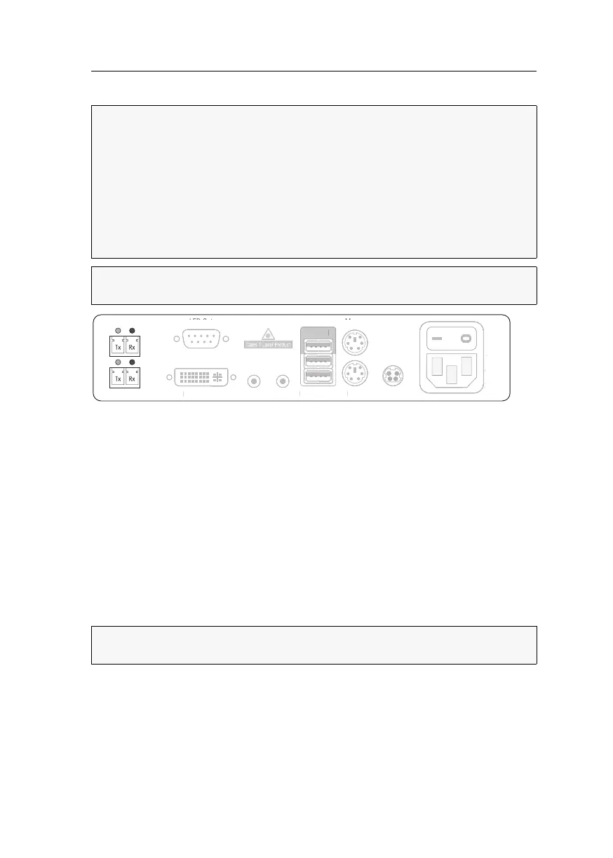
Main Power
LED Out
DVI/VGA OutTransmission 1
Transmission 2
Red. Power
Mouse
Keyb.Micro In
Speaker
Generic
Keyb./Mouse
a
n
owe
u
VI
V
A Ou
e
.
ower
ou
e
e
cro
S
eake
eneri
e
.
ous