4
Bender shoe will not
return when pressing
return and jog button.
Jog button
malfunctioning.
Unplug bender power cord. Perform continuity check on wire harness.
Attach leads to red and green wires, Depress override (jog) button.
*The colors described here are not present on the model B2000-7 and
B2000-8 pendant harness (B2000 SERIAL NUMBERS BEGINNING WITH
LETTERS “J” - “N” OR BENDERS MANUFACTURED AFTER 2007).
However, the same troubleshooting actions should be taken.
If continuity exists, check jog switch in pendant control, (Parts Not Available).
Remove cover, place leads on red and green wires at switch. Depress jog
switch. If there is continuity, replace switch (Parts Not Available).
Refer to “Circuit Board” in “DISASSEMBLY” section (page 8) for instructions
Wire harness to pendant
damaged.
If no continuity exists, fault lies in wire harness.
Replace wire harness. (Refer to Repair Parts List for illustration and
additional part numbers).
Refer to “Circuit Board” in “DISASSEMBLY” section (page 7) for instructions.
Pendant damaged or
malfunctioning.
Replace pendant switch, Part Number – PO5C
If model B2000-4 or older (SERIAL NUMBERS BEGINNING WITH LETTERS
“A” - “E” OR BENDERS MANUFACTURED BEFORE 2001), customer may
need to upgrade to current model B2000. Older model pendant switch is no
longer available.
For models B2000-5 and B2000-6 (SERIAL NUMBERS BEGINNING WITH
LETTERS “F” - “H” OR BENDERS MANUFACTURED BETWEEN 2001 AND
2004), customer may be able to adapt new pendant (P05C) to older models.
Bender shoe
successfully returns to
zero, indicator light on
top of Pendant Control
malfunctions and does
not light.
Zero limit switch is
malfunctioning and is
not receiving voltage.
Unplug bender power cord. Perform continuity check on harness from pendant
control. Attach leads to black and red wires.
Refer to “Circuit Board” in “DISASSEMBLY” section (page 5) for instructions.
If continuity exists, check the zero limit switch (see illustration in Repair Parts
List).
Attach the leads to black and red wires at the limit switch. Depress limit switch
actuator tab. If continuity exists, replace switch, Part Number- DA9687372.
Refer to “Limit Switch” in “DISASSEMBLY” section (page 7) for instructions.
Harness to switch is
malfunctioning and is
not receiving voltage.
Unplug bender power cord. Perform continuity check on wire harness
from limit switch.
If no continuity exists, the wire harness is malfunctioning.
Remove and strip wire harness wire ends, crimp on female terminals
(Part Number – 21-161F), and reconnect terminals to limit switches.
If problem continues, replace wire harness.
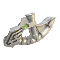
In order to replace the limit switch wire harness, the following components
need to be disassembled: bender shoe (item #1), sprocket (item #8),
end plate (item #26), and handle (item #38). Please refer to Figure 1 to
identify listed parts.
Refer to “Bender Shoe”, “Drive Sprocket”, and “Limit Switch” in
“DISASSEMBLY” section (pages 7 & 8) for instructions.
Bender consistently
develops over bends.
Bend angle is not
correctly indicated.
Ensure that the flat edge of the pointer (Part Number – 802950N) is on a line
indicating the exact degree of bend desired, not the angled edge. Failure to do
this will lead to inaccurate bends.
Refer to Instruction Sheet for operation instructions.
Bender zero adjustments
are necessary.
Ensure bender zero adjustment has been performed. This is required
after every re-assembly.
Refer to “ZERO SET ADJUSTMENT” section (page 10) for mechanical
adjustment instructions.
Bender angle
adjustments are
necessary.
Differences in conduit characteristics and other variations can lead to incorrect
scale indications. Loosen the size scale (for type material being bent) mounting
screws. Slide the scale clockwise as many degrees as the over bend (if bend is
5° over, move indicator 5° clockwise). The degree of movement is observed by
watching one of the size marks as it moves past the angle disc scale. Tighten
the mounting screws.
Refer to Instruction Sheet for more Angle Adjustment instructions.